Catheter and Surgical Ablation in the Therapy of Arrhythmias
Experience over the last decade has demonstrated that pharmacologic therapy for the management of paroxysmal ventricular and supraventricular arrhythmias may not be adequate and/or may be associated with significant proarrhythmic effects. The development of antitachycardia pacing techniques and, in particular, the recent development of implantable devices with antitachycardia pacing, cardioversion, and defibrillation capabilities at both an atrial and ventricular level have added a new dimension to our therapeutic armamentarium. These electronic devices are expensive, but more importantly, they are a treatment, not a cure of the disorder. Ideally, the preferred therapy for all arrhythmias would be to prevent their occurrence by either destroying or removing the tissue responsible for the arrhythmia. If that were not possible, indirect approaches such as isolating arrhythmogenic tissue from the remainder of the myocardium or modifying tissue passively involved, but contributing to the symptoms related to the arrhythmia (e.g., the A-V node in patients with atrial fibrillation and a rapid ventricular response), would be an alternative approach.
Over the past four decades, we have observed a rapid expansion of our knowledge of the pathophysiologic basis for arrhythmogenesis and have developed and refined electrophysiologic tools to localize the site of origin of such arrhythmias. The ability to identify the mechanism and/or site of origin of an arrhythmia provides the rationale for surgical or catheter-based ablative techniques to treat the arrhythmias. The use of the electrophysiologic techniques of programmed stimulation and catheter based as well as intraoperative mapping led to the evolution of electrophysiologically guided surgical techniques to deal with specific arrhythmias, the first of which was the Wolff–Parkinson–White syndrome.1,2 This was followed by the development of new surgical approaches for the management of a variety of supraventricular and ventricular arrhythmias.3,4,5,6,7,8,9,10,11,12,13,14,15,16 Subsequently, catheter-based methods of ablating myocardial tissue were developed to control and/or cure many tachyarrhythmias for which surgery had become the only mode of therapy.17,18,19,20 Today catheter ablation has replaced surgery as a first-line therapy to “cure” most supraventricular and ventricular tachycardias. Techniques using electric, thermal (hot or cold), light (laser), mechanical (ultrasound), and chemical methods of ablation have been developed, some of which are already being used clinically. The exact mechanisms of damage of any given technique are complex and involve multiple biophysical and/or chemical factors, depending on the method employed. Although our knowledge of the biophysical factors responsible for producing electrophysiologic changes in arrhythmogenic tissue is limited, the experimental basis for tissue injury by these various techniques has been studied and reviewed.17,18,19,20,21,22,23
Several steps must be taken for catheter ablation techniques to be successful. These steps include (a) accurate localization of the arrhythmogenic tissue; (b) delivery of the ablative electric field, heat, cold, light, or chemicals to the appropriate site in the heart; (c) transfer of the ablative factors from the interface of the catheter and the tissue to the arrhythmic site, which may be deep in the myocardium; (d) production of damage to arrhythmogenic tissue; which (e) results in electrophysiologic changes in the arrhythmogenic tissue, which render it nonarrhythmogenic. All of these factors require a better understanding if successful and accurate catheter ablation techniques are to be developed. The catheter-based ablative techniques that have been employed clinically or are currently under clinical investigation include (a) electrical deflagratory shocks (fulguration)—damage done by electrical current disruption of membranes, barotrauma, and thermal injury; (b) nonarcing electrical shocks (electroporation)—damage done by current to disrupt membranes and thermal injury;24,25,26 (c) laser—thermal damage resulting in either surface vaporization (argon laser) or photocoagulation (neodymium: YAG laser); (d) radiofrequency (RF)—thermal injury and desiccation;21,27 (e) microwave—thermal injury and desiccation; (f) chemical destruction of tissue; (g) focused ultrasound; and (h) cryothermal ablation. While some of these techniques have been used during surgery (i.e., laser, cryoablation, and electric shocks), there has been an increasing interest in their use in catheter delivery systems. Catheter-delivered DC ablation (arcing and nonarcing) was the initial method used but has largely been replaced by RF ablation, which will be the basis for discussion in this chapter. It is impossible and impractical to discuss the biophysical basis of all these techniques, which will continue to evolve over the next decade.
The main focus of this chapter is the role of the electrophysiologist in the management of arrhythmias by surgical and catheter-based ablation. The electrophysiologist must select the appropriate patients, choose the technique available
that offers the highest rate of success with lowest morbidity to that patient, and most importantly, accurately localize the tissue to be ablated. The most important and critical job of the electrophysiologist is to accurately identify the arrhythmogenic tissue to be removed or destroyed through the use of catheter or intraoperative mapping, or both. Success of any ablative technique depends on accurate localization of the source of the arrhythmia. As such, this chapter will mainly concentrate on how one defines arrhythmogenic tissue and how one can approach destruction or removal of this tissue by catheter-based or surgical techniques. Brief descriptions of the specific ablative techniques used are given in the following paragraphs.
that offers the highest rate of success with lowest morbidity to that patient, and most importantly, accurately localize the tissue to be ablated. The most important and critical job of the electrophysiologist is to accurately identify the arrhythmogenic tissue to be removed or destroyed through the use of catheter or intraoperative mapping, or both. Success of any ablative technique depends on accurate localization of the source of the arrhythmia. As such, this chapter will mainly concentrate on how one defines arrhythmogenic tissue and how one can approach destruction or removal of this tissue by catheter-based or surgical techniques. Brief descriptions of the specific ablative techniques used are given in the following paragraphs.
Biophysics of Current Ablation Techniques
Catheter ablation techniques have been so successful in treating a variety of arrhythmias that they have almost totally replaced operative approaches to the management of supraventricular and ventricular arrhythmias. Of the several modes of ablation available, RF ablation is by far the most commonly used, having replaced DC ablation for more than two decades because of improved efficacy and safety. Nevertheless DC ablation remains in use at some institutions. Our understanding of the biophysics of lesion creation is almost completely based on studies using energy delivery in model systems with normal myocardium. Unfortunately there is little data or understanding of how energy delivery changes in the presence of myocardial scar.
DC Ablation
With DC ablation, the electrical energy is delivered through either a catheter or a hand-held probe in the operating room. The energy delivered is from a standard defibrillator/cardioverter in most cases. Most standard defibrillator/cardioverters deliver between 1 and 3 kV to a specific electrode to which the device is connected. Although a variety of waveforms are used in different defibrillators, most commonly peak voltage is achieved in 1 to 2 msec, which is associated with a peak current flow of 40 to 60 amperes shortly thereafter. In most instances, a single electrode (usually the tip of a catheter) is used as the cathode, and an indifferent backplate serves as an anode sink for the discharge. This technique allows the delivery of high-energy shocks in the range of 100 to 400 J per shock. When DC catheter ablation is performed using a standard defibrillator, a vapor globe is initially formed as a result of electrolysis. This globe subsequently expands and becomes ionized, ultimately resulting in arcing. The arcing is associated with extremely high temperatures and a veritable concussive explosion in the heat. The explosion can be thought of in terms of a compressive shock that is due to the formation of a vapor globe within noncompressible blood, followed by rebound shocks with the collapse of the globe. High-speed cinematography has shown dramatic changes in cardiac shape during this “explosion.” The arcing explosion has led to the widespread use of the term fulguration for this type of catheterization. According to Fontaine et al.,28 a shock energy of 40 to 160 J produces pressure waves of 2.5 to 7.5 atmospheres.
If one measures current and voltage during the delivery of the discharge, there will be a sudden increase in voltage and decrease in current as the vapor globe forms, as a result of a rise in impedance. The high temperature of the electrical arc, which may approach several thousand degrees, results in pitting of the distal and occasionally more proximal electrodes of the catheter. Despite the high temperature associated with the arc, there is insignificant heating of the tissue, suggesting that thermal damage is not the primary mechanism by which the fulguration works. There is still debate as to the relative role of barotrauma and the effects of the high-energy electrical field of the DC shock as the cause of the ultimate pathologic damage and electrophysiologic sequelae. Most investigators believe that it is the direct electrical effect that disrupts myocardial membranes, resulting from either dielectrical breakdown, change in membrane lipids, or physical compression and mechanical disruption of the membrane.29 Using cultured myocytes, Jones et al.30 demonstrated that the delivery of 200 V/cm can affect membrane depolarization, which may represent membrane breakdown with higher-energy discharges.
Barotrauma is undesirable, despite the fact that it may play a role disrupting and/or separating myocardial fibers in some types of ablation. Barotrauma associated with fulguration has consistently caused rupture of the coronary sinus when energy is delivered there and has been associated with rupture of other cardiac structures, myocardial dysfunction, and arrhythmias.28,29,30,31,32 Experimental studies have shown that the extent of damage that is produced by DC shocks is directly related to the amount of energy delivered.19,28,31,32,33,34,35,36 The integrity of catheters is frequently disrupted in the caring process, which is due to the transient high temperatures.28,33,37 Arcing not only affects the distal tip but can also result in damage to more proximal electrodes, since a high-voltage gradient is formed between the distal electrode and more proximal ring electrodes by the expanding vapor globe. Bardy et al.37 have shown that following the first large shock the dielectric strength of catheters was reduced. A greater disruption is seen when proximal electrodes are used to deliver the energy instead of the distal tip. Thus, there is reasonable evidence that most electrode catheters demonstrate some current leakage, particularly when multiple shocks are delivered. This may lead to misdirected shocks and clinical failures, as well as to unnecessary barotrauma. No catheter has ever been FDA-approved for DC ablation. More work is necessary to develop catheters capable of withstanding fulguration-type shocks if this technique is going to be used in the future. This is unlikely to occur.
Pathologically, fulguration shocks produce a somewhat patchy contraction band necrosis. The volume of damage done generally correlates with the amount of energy delivered and is relegated to the electric field.31,32,34 Perhaps it is the patchiness
of the damage that apparently makes the tissue more arrhythmogenic than the homogeneous necrosis associated with cryothermal or RF injury.
of the damage that apparently makes the tissue more arrhythmogenic than the homogeneous necrosis associated with cryothermal or RF injury.
Irreversible electroporation is a new variation of electrical ablation. In this technique, cell membranes are exposed to high-voltage electrical fields, resulting in nonthermal, nonbaratraumatic damage to the cell membrane resulting in cell death. In experimental ablation studies, this technique appears to be relatively specific for myocardial tissue damage. du Pre and coworkers delivered electroporation discharges (50 to 360 J, using a standard monophasic defibrillator) to the epicardium intentionally over the left anterior descending coronary artery. At 3 weeks, intimal hyperplasia was not detected and coronary angiography demonstrated no stenosis.38 Neven and colleagues delivered catheter-based electroporation discharges (50 to 200 J) to the epicardium using a percutaneous subxyphoid approach which resulted in transmural lesions without acute effects on coronary arteries.25 Obviously, additional research is necessary, but this may result in a powerful new ablation technique.
Radiofrequency Energy
RF energy is generated as an alternating current at a frequency of 300 to 750 kHz (range 100 to 2,000 kHz) delivered between the tip of an ablation catheter and a cutaneous patch.39 The sinusoidal waveform creates a potential difference between the cutaneous patch and the catheter tip, which alternates in polarity. Because of the small surface area of the tip of the catheter relative to the cutaneous patch, the current density will be high at the tip and low at the patch. During RF application electrical energy is converted to thermal energy by resistive heating. The heat that is generated is transferred to the subjacent cardiac tissue primarily by conduction and to a minor extent by radiation, which decreases by the fourth power of the distance from the catheter tip. Heat is simultaneously dissipated by convection into the blood pool. Since the catheter tip–myocardial interface is the major resistor in this AC circuit, current density and heat are greatest at the catheter tip and minimal at the cutaneous patch. Effective heating of the myocardium is critically dependent on catheter contact and stability as well as on the surface area of the catheter tip. Poor contact or stability will lead to heat loss to the blood pool and failure to generate adequate myocardial temperatures despite application of high voltage/power. Although a larger surface area (length of the catheter tip electrode) can lead to greater lesion size, it will require delivery of greater power, since the greater surface area will be subjected to greater convective heat loss to the blood pool to which it has greater exposure. Thus maximum lesion size using a 4- to 5-mm ablation tip can be accomplished using a maximum power of 50 W while up to 100 W may be required to achieve maximal lesion size using an 8- to 10-mm catheter tip. Electrodes of 4 to 5 mm through which the RF energy is delivered provide the best control and most reasonably sized lesion to accomplish the tasks of catheter ablation for most paroxysmal supraventricular arrhythmias.40,41,42,43 The size of the lesions produced by RF are smaller than those associated with fulguration; moreover, scar tissue limits the ability to transfer thermal energy, making RF ablation of ventricular arrhythmias associated with scarred endocardium more difficult. A variety of deflectable catheters are available that can have different arcs of curvature, bidirectional deflecting capabilities (with similar or different lengths of deflection), rotational capability, or magnetic sensors (Biosense) that allow for precise localization in three dimensions (Fig. 13-1).
RF ablation results in thermal injury with coagulation necrosis and desiccation when tissue heating exceeds approximately 50°C for at least 10 seconds.20,21,22,23,39,40 Application of RF energy results in a lesion with a volume half-time of ≈8 seconds and maximum volume achieved in 30 to 40 seconds. As heat is produced at the catheter-myocardial interface the impedance drops. A drop of impedance of 5 to 10 Ω is a sign of conductive heating to the subjacent tissue. The lesion is smaller than that seen with DC ablation and is more homogeneous. If the temperature at the electrode-myocardial interface increases excessively, a rise in impedance develops because of gas formation caused by vaporization of the blood around the catheter tip. A drop in current necessarily occurs with an impedance rise. Impedance rise also causes formation of coagulum on the catheter tip, and it is mandatory to remove the catheter and wipe off the coagulum, which is a potential source of emboli. If the tissue is heated to >100°C, steam will be generated as a consequence of boiling within the myocardium. This often can be detected as an audible popping sound, which will just precede a marked rise in impedance. The steam can produce myocardial rupture and subsequent tamponade. Smaller tears may also occur. Various catheter modifications have been evaluated to optimize the size of the lesions and control the lesions produced by the RF.
The initial modification of ablation catheters was use of thermocouples or thermistors imbedded near the catheter tip
to provide information as to the temperature generated at the tip of the catheter at any given power. This modification was deemed necessary because of the inability to relate the power used to tissue heating. These are closed loop-temperature control systems such that the power is automatically adjusted to maintain a desired temperature. Such a system allows for the maintenance of electrode temperature despite changes in catheter contact produced by respiration or unstable catheter position. Such control of temperature largely (but not entirely) avoids the formation of coagulum. Unfortunately, the thermistor or thermocouple does not accurately provide information about tissue temperature. Due to convective heat loss to the blood the temperature recorded at the catheter tip may give a falsely low reading relative to tissue temperatures achieved if inadequate catheter contact is present. This might result in intramyocardial tissue boiling and steam production (see above). Thus, to assure that excessive intramural heating does not take place, target temperatures should be set at 55° to 65°C.
to provide information as to the temperature generated at the tip of the catheter at any given power. This modification was deemed necessary because of the inability to relate the power used to tissue heating. These are closed loop-temperature control systems such that the power is automatically adjusted to maintain a desired temperature. Such a system allows for the maintenance of electrode temperature despite changes in catheter contact produced by respiration or unstable catheter position. Such control of temperature largely (but not entirely) avoids the formation of coagulum. Unfortunately, the thermistor or thermocouple does not accurately provide information about tissue temperature. Due to convective heat loss to the blood the temperature recorded at the catheter tip may give a falsely low reading relative to tissue temperatures achieved if inadequate catheter contact is present. This might result in intramyocardial tissue boiling and steam production (see above). Thus, to assure that excessive intramural heating does not take place, target temperatures should be set at 55° to 65°C.
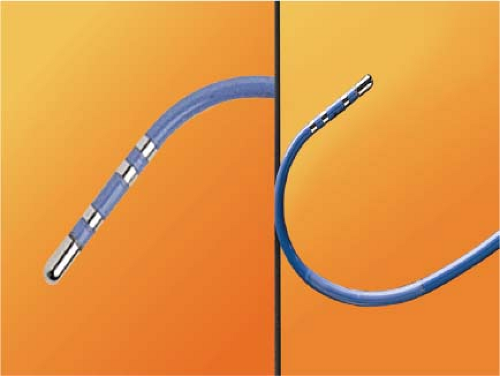 FIGURE 13-1 Standard ablation catheter with bidirectional curves. Ablation catheters typically have 4- to 5-mm tips and can be deflected in a variety of different manners. This particular catheter has deflection capabilities in two directions with different curves in each direction. |
Another modification to increase lesion size has been the development of irrigated catheters (Fig. 13-2). As discussed above, delivery of heat energy is limited because interface temperatures cannot exceed 100°C. By cooling the catheter tip more voltage can be applied without a rise in temperature at the catheter-myocardial interface. This results in a greater current density at the catheter-tissue interface, which results in a larger volume (and depth) of tissue heated by conduction.27 While cool-tip catheters can produce larger lesions, one cannot control the lesion size by assessing catheter tip temperature, since it is constantly being cooled. Excessive tissue heating, steam formation, and myocardial rupture can easily occur if the tip temperature is allowed to get too high. As a result, I recommend using impedance as the main method of assessing lesion formation. A 10-Ω drop in impedance is ideal, and this occurs despite maintaining catheter tip temperature at <42°C. The method of cooling varies from an internal counter-current system to catheters in which the saline is flushed through a lumen at the tip of the catheter or through pores at the tip of the catheter. Experimental data suggest the cool-tip saline spray catheter may produce less char and thrombus than the internally cooled catheter.44 Whether this has clinical relevance is untested. The latter two methods necessarily result in introducing a variable amount of saline into the circulation blood volume depending on the number of and time over which the lesions are given. Recently, several companies have redesigned irrigation catheters to have more irrigation ports which allow effective ablation at lower rates of saline flow (Thermocool SF Biosense, Sapphire St. Jude Medical).
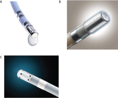 FIGURE 13-2 Externally irrigated catheters. Several companies manufacture ablation catheters that provide external irrigation. The Thermocool (Biosense Webster) catheter (A), was the first catheter approved for the ablation of atrial fibrillation; it uses six irrigation ports at the tip of the catheter. The Thermocool SF (Biosense Webster) catheter (B) has many more delivery ports and allows a smaller volume of saline irrigation. The Safire BLU (St. Jude Medical) catheter (C) has six irrigation ports at the tip of the catheter. (Images A and B courtesy of Biosense Webster; image C courtesy of St. Jude Medical.) |
Phased RF energy delivery is an old idea that has been recently rediscovered. Multipolar catheters can be configured to deliver duty-cycled unipolar and bipolar (between adjacent electrodes) RF energy. At present, two companies manufacture phased RF catheters designed for ablation of atrial fibrillation (PVAC Medtronic, EnMARQ Biosense), and clinical trials are ongoing. Early trials of one device demonstrated more frequent development of asymptomatic cerebral lesions detected on diffusion weighted magnetic resonance imaging (MRI) of the brain, as compared to other ablation energy systems.45,46,47 Clinical trials continue to determine if catheter redesign and/or irrigation with moderate risk.
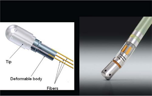 FIGURE 13-3 Force sensing catheters. The TactiCath Quartz ablation catheter (St. Jude Medical) provides real-time contact force and vector measurements based on light interferometry. The SmartTouch catheter (Biosense Webster) utilizes a precision spring in the catheter tip; spring displacement proportional to tip contact force/vector. (Images courtesy of St. Jude Medical and Biosense Webster, respectively.) |
The major advantages of RF energy are absence of barotrauma, lack of requirement of general anesthesia, lack of muscle stimulation, and the ability to control very focal injury. It is because of these factors that RF ablation has supplanted fulguration as the method of ablation in most centers. Another advantage of RF ablation is the fact that intracardiac electrograms may still be recorded throughout the procedure; and following delivery of RF energy, the catheter electrodes function perfectly to record and stimulate. Nevertheless, RF techniques remain limited by the requirement of good contact to achieve appropriate damage and by the fact that the extent of tissue damage is not predictable.
Recently the limitation of contact has been addressed by real-time measurement of contact force (Fig. 13-3). Clinical trials of force sensing catheters for ablation of atrial fibrillation showed that unblinded access to real-time data produced meaningful improvements in freedom from atrial fibrillation in short-term follow-up.48,49,50,51,52 Theoretically, lesions are formed by the intersection of contact force, power, and time and new dosing strategies are being developed to try to make lesion delivery more uniform and permanent.
Laser Ablation
Lasers have been used in surgery for many years. In the past decade, there has been interest in using lasers intraoperatively for the management of ventricular arrhythmias or the creation of A-V block.53,54,55,56,57 There has also been an interest, however, in the development of catheter delivery of laser light.58 The mechanism by which laser ablation works is based on heat generation within tissue by the conversion of light energy into thermal energy. Depending on the laser used, the distribution of light within the tissue and the degree and site of destruction are quite variable and highly dependent on the wavelength. The two major laser systems used are argon laser light, which has a wavelength of 500 nM, and the ND:YAG laser, which has a wavelength of 1,060 nM. With the argon laser, the light energy is absorbed rapidly in the first few millimeters of tissue, resulting in surface vaporization with crater formation. In contrast, the ND:YAG laser is associated with significant scatter in tissue, causing more diffuse and deeper tissue injury resulting in photocoagulation necrosis. Lee et al.59 compared the electrophysiologic effects of the ND:YAG laser with DC shock in normal canine left ventricular endocardium. While the pathologic responses were similar qualitatively, the laser lesions were associated with less ventricular arrhythmias. The gross lesions produced by 40 to 80 J of laser energy were comparable to lesions produced by 100 to 200 J of DC shock in volume; however, lesions produced by the ND:YAG laser are homogeneous and well circumscribed (Fig. 13-4). The advantages of laser-delivered energy are that it takes a short period of time to deliver and the amount of energy delivered can be easily controlled. However, if catheter delivery systems are to be developed, contact issues with the endocardium, the site in the heart at which ablation is to take place (e.g., venous and arterial blood absorb laser energy to different degrees), and the ability to focus the laser on the specific target are issues that need further resolution. A laser balloon delivery system (Cardiofocus) which could allow tissue visualization (to ensure contact) is currently under investigation (Fig. 13-5).60 A recent multicenter study reported pulmonary vein isolation using this system in 200 patients with paroxysmal atrial fibrillation. Acute isolation was obtained in 98.8% of PVs with reasonable procedural times (200 ± 54 minutes); complications included a 2% incidence of tamponade and a 2.5% incidence of phrenic nerve palsy. Freedom from AF at 12 months off antiarrhythmic drugs was 60.2%.61 Cost may be a limitation to laser therapy.
Cryoablation
Cryoablation has been used in the surgical treatment of a variety of arrhythmias for over 30 years. Well-demarcated, homogeneous lesions produced by endocardial or epicardial
application are similar to those produced by the ND:YAG laser (Fig. 13-4). The lesions produced preserve the underlying fibrous structure, so they are inherently stronger and less likely to rupture than RF lesions. They were also apparently nonthrombogenic (e.g., no emboli in the absence of anticoagulation). While near transmural lesions can be produced intraoperatively using temperatures of −60°C in the presence of cold cardioplegia, achievement of such lesions with a catheter-based delivery system has not been definitively established at this time. However, several companies have developed catheter-based cryodelivery systems, which improved energy delivery based on phase change (liquid nitrogen to gas) within the catheter tip.62 The blood pool is a major impediment to achieving temperatures necessary to create permanent lesions that are adequate in size using cryothermia. Catheter-based delivery systems are used for ablation of A-V nodal tachycardia and paraseptal bypass tracts, particularly in children. Cryoablation has the advantage of cryoadherence once energy is delivered, which eliminates unwanted catheter movement; however, recurrence rates with cryoablation have been higher than with RF energy.63 A cryoballoon catheter has been developed for pulmonary vein isolation (Artic Front Medtronic) (Fig. 13-6). This design obviates some of the difficulty with local blood flow as the balloon structure occludes the pulmonary vein being ablated. A randomized trial in 245 patients with atrial fibrillation (78% paroxysmal) demonstrated superior efficacy of cryoablation compared to antiarrhythmic drug treatment, with similar success rates as would have been expected with RF energy ablation; however, phrenic nerve palsy, which is typically temporary, was observed in 11% of patients.64 A second-generation catheter (Artic Front Advance Medtronic as well as improved cryoablation “dosing” are expected to improve efficacy and reduce phrenic nerve damage.
application are similar to those produced by the ND:YAG laser (Fig. 13-4). The lesions produced preserve the underlying fibrous structure, so they are inherently stronger and less likely to rupture than RF lesions. They were also apparently nonthrombogenic (e.g., no emboli in the absence of anticoagulation). While near transmural lesions can be produced intraoperatively using temperatures of −60°C in the presence of cold cardioplegia, achievement of such lesions with a catheter-based delivery system has not been definitively established at this time. However, several companies have developed catheter-based cryodelivery systems, which improved energy delivery based on phase change (liquid nitrogen to gas) within the catheter tip.62 The blood pool is a major impediment to achieving temperatures necessary to create permanent lesions that are adequate in size using cryothermia. Catheter-based delivery systems are used for ablation of A-V nodal tachycardia and paraseptal bypass tracts, particularly in children. Cryoablation has the advantage of cryoadherence once energy is delivered, which eliminates unwanted catheter movement; however, recurrence rates with cryoablation have been higher than with RF energy.63 A cryoballoon catheter has been developed for pulmonary vein isolation (Artic Front Medtronic) (Fig. 13-6). This design obviates some of the difficulty with local blood flow as the balloon structure occludes the pulmonary vein being ablated. A randomized trial in 245 patients with atrial fibrillation (78% paroxysmal) demonstrated superior efficacy of cryoablation compared to antiarrhythmic drug treatment, with similar success rates as would have been expected with RF energy ablation; however, phrenic nerve palsy, which is typically temporary, was observed in 11% of patients.64 A second-generation catheter (Artic Front Advance Medtronic as well as improved cryoablation “dosing” are expected to improve efficacy and reduce phrenic nerve damage.
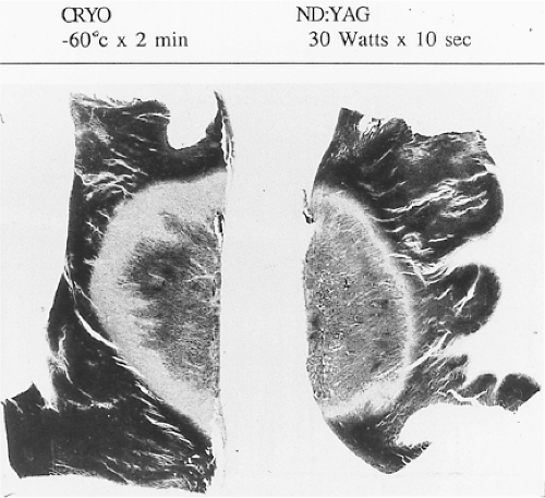 FIGURE 13-4 Comparison of lesions produced by cryoablation and ND:YAG photocoagulation. Both cryoablation and ND:YAG laser photocoagulation produce circumscribed, homogeneous necrosis. (From Svenson RH, Gallagher JJ, Selle JG, et al. Neodymium: YAG laser photocoagulation of ventricular tachycardia: rationale, method of application, and results in 17 patients. In: Breithardt G, Borggrefe M, Zipes DP, eds. Nonpharmacological therapy of tachyarrhythmias. Mt. Kisco, NY: Futura Publishing, 1987:181, with permission.) |
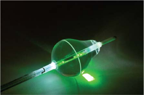 FIGURE 13-5 The Endoscopic Ablation System (HeartLight, CardioFocus) is a compliant balloon–based laser delivery system, equipped with a 500 micron endoscope to allow lesion visualization. (Image courtesy of CardioFocus.) |
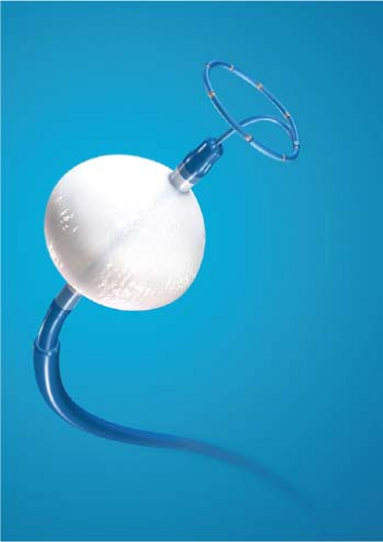 FIGURE 13-6 The cryoballoon catheter (Artic Front Advance, Medtronic) which can be deployed to the pulmonary veins over a wire or utilizing a multielectrode circular catheter (Achieve, as shown). (Image courtesy of Medtronic, Inc.) |
Ultrasound
Ultrasound energy converts mechanical energy to heat. The frequency required to produce destructive lesions ranges from
4 to 9 MHz. Ultrasound can be focused, and therefore has the unique property of not requiring tissue contact. Preliminary studies have applied ultrasound to the ablation of focal triggers by isolating the pulmonary vein from the atrial myocardium using ultrasound delivered via a balloon placed in a pulmonary vein.65 Experience with this first-generation device was not favorable, both in terms of poor efficacy and an unacceptable rate of pulmonary vein stenosis. A second-generation forward firing device which delivered high-intensity focused ultrasound (Prorhythm) was removed from clinical use because of a high incidence of procedural complications, particularly atrioesophageal fistula.66 Directional focused ultrasound delivery systems (Epicor St. Jude Medical) are still utilized in surgical ablation of atrial fibrillation.
4 to 9 MHz. Ultrasound can be focused, and therefore has the unique property of not requiring tissue contact. Preliminary studies have applied ultrasound to the ablation of focal triggers by isolating the pulmonary vein from the atrial myocardium using ultrasound delivered via a balloon placed in a pulmonary vein.65 Experience with this first-generation device was not favorable, both in terms of poor efficacy and an unacceptable rate of pulmonary vein stenosis. A second-generation forward firing device which delivered high-intensity focused ultrasound (Prorhythm) was removed from clinical use because of a high incidence of procedural complications, particularly atrioesophageal fistula.66 Directional focused ultrasound delivery systems (Epicor St. Jude Medical) are still utilized in surgical ablation of atrial fibrillation.
Control of Supraventricular Arrhythmias by Ablative Techniques
The development of surgical techniques to cure arrhythmias began with the first successful electrophysiologically directed cure of the Wolff–Parkinson–White syndrome. This took place in 1968, when Dr. Will Sealy successfully divided an A-V bypass tract localized to the right lateral A-V groove by epicardial mapping.1,2 This event initiated the development of surgical techniques to manage the Wolff–Parkinson–White syndrome,3,4,5,6,7,8,9 and subsequently, led to the development of innovative surgical interventions for the treatment of A-V nodal reentrant tachycardia, atrial tachycardias, and atrial flutter/fibrillation.5,10,11,12,13,67,68,69,70,71,72,73,74 Cryothermal injury, electrical shock, and lasers have also been used intraoperatively to manage these arrhythmias.28,33,75,76,77,78,79 In the past three decades, catheter-delivered ablative techniques have been developed to manage arrhythmias that had previously required surgical intervention. In fact, the widespread use of catheter ablation techniques has virtually eliminated the need for surgery to manage drug-resistant supraventricular tachycardias that are due to the Wolff–Parkinson–White syndrome and A-V nodal reentry, and A-V junctional ablation, which represents of course an indirect treatment of atrial fibrillation in terms of control of the ventricular response.80,81,82,83,84,85,86,87,88,89,90,91,92,93,94,95,96,97,98,99,100
Localization of the arrhythmogenic substrate and defining the mechanism of arrhythmias has led to the development of these techniques and will be the focus of the discussion in this and subsequent sections. The major role of surgery today is for the “cure” of atrial fibrillation as a primary procedure or as an adjunct to valvular surgery (see below).
Ablation of Atrioventricular Bypass Tracts and Variants of Pre-excitation
Successful ablation of atrioventricular bypass tracts requires precise localization of the atrial and/or ventricular insertion site of the bypass tract. As noted in Chapter 10, A-V bypass tracts may occur anywhere around the tricuspid and mitral annulae except for the region of aortomitral continuity, at which no ventricular myocardium lies below the atrium. The anatomy of right-sided and left-sided bypass tracts differs somewhat (Fig. 13-7). The tricuspid annulus has a greater circumference (approximately 12 cm) than the mitral annulus (approximately 10 cm) and is not a complete fibrous ring, but may have many regions of discontinuity. This obviously
means that the entire tricuspid annulus must be mapped in detail to accurately located right-sided pathways, whereas only approximately three-fourths of the mitral annulus needs to be mapped for left-sided pathways, because of the absence of pathways in the region of aortomitral continuity. Moreover, there is a folding over the atrium and ventricle, as shown in Figure 13-7, such that it may be difficult to position the catheter at the tricuspid annulus because of a tendency of the catheter to fall into the folded over “sac.” Since bypass tracts can connect between atrium and ventricular anywhere along the folded sac, bypass tracts may be somewhat removed from the annulus: making accurate localization of the atrial insertion site critical to successful ablation. An annular ablation at a site that is nearly at the annulus may fail because the atrial insertion site may be as far as 1 cm away from the annulus in the folded-over atrial sac. This folded-over atrium and bizarre angle required for mapping of the inferior and posterolateral aspects of the right atrium may make mapping of this region difficult using an inferior cava approach. Thus, in some cases a superior vena cava approach may be required to allow full exploration of the “folded-over atrial sac” and the inferior, inferoanterior (formerly referred to as inferolateral) and lateral positions around the tricuspid annulus. The standard inferior vena cava approach, however, is quite adequate to map the superior aspects of the tricuspid ring. Because of the anatomic variability of the right-sided A-V rings, Swartz et al.101 have recommended insertion of a small catheter in the right coronary artery, which can be used to map the entire A-V ring since the coronary artery remains in constant relationship to the ring. This may be useful in patients with Ebstein anomaly in which the triscupid valve is displaced into the ventricle or in patients who have had multiple unsuccessful attempts at ablation of right-sided pathways. I do not believe a right coronary catheterization should be used routinely, and in fact should be discouraged, since it has potential disastrous consequences. There has been no long-term follow-up of coronary arteries in patients in whom this procedure has been performed, and there should be serious concern regarding endothelial abrasion by such a catheter, resulting in initiation of an atherogenic process. In my opinion, careful and detailed mapping with standard ablation catheters is adequate. A guiding sheath is particularly useful when an inferior vena cava approach to an inferoanterior bypass tract is utilized. Use of a halo catheter or a multipolar catheter positioned around the tricuspid annulus can provide very good regional localization capabilities to guide the roving ablation catheter (Fig. 13-8). These multipolar catheters are used in an analogous fashion to coronary sinus catheterization for left-sided pathways (see below).
means that the entire tricuspid annulus must be mapped in detail to accurately located right-sided pathways, whereas only approximately three-fourths of the mitral annulus needs to be mapped for left-sided pathways, because of the absence of pathways in the region of aortomitral continuity. Moreover, there is a folding over the atrium and ventricle, as shown in Figure 13-7, such that it may be difficult to position the catheter at the tricuspid annulus because of a tendency of the catheter to fall into the folded over “sac.” Since bypass tracts can connect between atrium and ventricular anywhere along the folded sac, bypass tracts may be somewhat removed from the annulus: making accurate localization of the atrial insertion site critical to successful ablation. An annular ablation at a site that is nearly at the annulus may fail because the atrial insertion site may be as far as 1 cm away from the annulus in the folded-over atrial sac. This folded-over atrium and bizarre angle required for mapping of the inferior and posterolateral aspects of the right atrium may make mapping of this region difficult using an inferior cava approach. Thus, in some cases a superior vena cava approach may be required to allow full exploration of the “folded-over atrial sac” and the inferior, inferoanterior (formerly referred to as inferolateral) and lateral positions around the tricuspid annulus. The standard inferior vena cava approach, however, is quite adequate to map the superior aspects of the tricuspid ring. Because of the anatomic variability of the right-sided A-V rings, Swartz et al.101 have recommended insertion of a small catheter in the right coronary artery, which can be used to map the entire A-V ring since the coronary artery remains in constant relationship to the ring. This may be useful in patients with Ebstein anomaly in which the triscupid valve is displaced into the ventricle or in patients who have had multiple unsuccessful attempts at ablation of right-sided pathways. I do not believe a right coronary catheterization should be used routinely, and in fact should be discouraged, since it has potential disastrous consequences. There has been no long-term follow-up of coronary arteries in patients in whom this procedure has been performed, and there should be serious concern regarding endothelial abrasion by such a catheter, resulting in initiation of an atherogenic process. In my opinion, careful and detailed mapping with standard ablation catheters is adequate. A guiding sheath is particularly useful when an inferior vena cava approach to an inferoanterior bypass tract is utilized. Use of a halo catheter or a multipolar catheter positioned around the tricuspid annulus can provide very good regional localization capabilities to guide the roving ablation catheter (Fig. 13-8). These multipolar catheters are used in an analogous fashion to coronary sinus catheterization for left-sided pathways (see below).
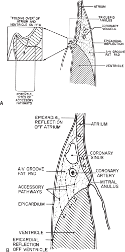 FIGURE 13-7 Anatomy of the right and left A-V rings. A: The right atrioventricular (A-V) ring is schematically shown with a blow-up of the annular region. The ring is incomplete and the atrium “folds” over the ventricle producing a sack. B: The left A-V ring is solid, and the relationship of the coronary sinus, coronary artery, and potential bypass tracts are shown. The anatomy of both A-V rings differs and has led to different ablation approaches for right- and left-sided bypass tracts. See text for discussion. (From Ferguson TB Jr, Cox JL, Surgical treatment for the Wolff–Parkinson–White syndrome: the endocardial approach. In: Zipes DP, Jalife J, eds. Cardiac electrophysiology: from cell to bedside. Philadelphia, PA: WB Saunders, 1990:697–907.) |
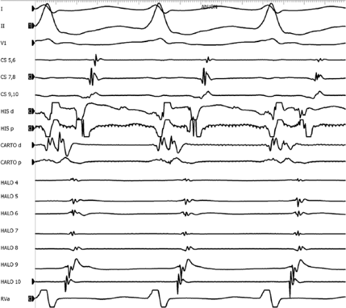 FIGURE 13-8 Use of a multielectrode catheter to assist mapping of tricuspid annulus in a patient with an anterior septal accessory pathway. Three surface leads and intracardiac recordings from the CS, His, ablation (Carto), and a multipolar Halo catheter are shown during orthodromic tachycardia. As is the case in this recording, it is often difficult to position the Halo catheter at the tricuspid annulus (as demonstrated by the large atrial and absent ventricular signals). Nonetheless, this technique allows for rapid regionalization (earliest atrial recording on Halo 10), and a point of reference in terms of location and timing for the mapping catheter, which has an annular signal with much earlier atrial activation. |
On the left side of the heart, there is no significant folding over of the atrium and ventricle on each other, and a mitral annulus is a continuous fibrous structure. Initial mapping of the left atrial insertion sites of bypass tracts can be accomplished via the coronary sinus with standard 10 to 20 pole catheters with 2- to 5-mm interelectrode spacing. One must recognize that the coronary sinus has a variable relationship to the mitral annulus. Since the mitral valve is a posterior structure (i.e., relative to the tricuspid valve), the appropriate nomenclature for left-sided pathways is superior, inferior, superoposterior, posterior, and inferoposterior. Attempts at reforming electrophysiologists’ anatomical descriptions have
not been well accepted, however (Fig. 13-9).102 In all patients the proximal portion of the coronary sinus lies at least 2 cm superior to the annulus as it crosses the right to left atrium producing a pyramid-shaped space between the coronary sinus (base of the pyramid), the right and left atrium (sides of the pyramid), and central fibrous trigone (apex of the pyramid). Superiorposteriorly (formerly called anterolaterally), it frequently overrides the left ventricle, although there is significant variability of the relationship between the coronary sinus and the mitral annulus from the posterior portion to the anterior portion (see Chapter 10). Thus the coronary sinus may lie above the annulus and be associated with the left atrium itself, or may cross over to the ventricular side of the annulus. Thus, electrograms recorded from coronary sinus only can provide a reference for the atrial and/or ventricular (in the case of overt pre-excitation) insertion sites of the bypass tract. As such, these electrograms can only be used to guide the ablation catheter to areas in which more detailed mapping can be performed. In addition, there are occasional anomalies of the coronary sinus, such as diverticuli, which may form the conduit for bypass tracts. In such cases, the bypass tract is epicardial and the ablation may need to be carried out in the coronary sinus, in which the earliest atrial activity during circus movement tachycardia or bypass tract potentials is found (see subsequent discussion on mapping). Conduction at the insertion sites of bypass tracts is markedly anisotropic, which is due to the nearly horizontal orientation of atrial and ventricular fibers as they insert into the mitral annulus. In addition, the atrial fibers run parallel to the annulus giving rise to rapid conduction away from the insertion site, parallel to the annulus, and slow conduction to the free wall of the atrium, perpendicular to the annulus. This has been demonstrated by Smeets et al.103 using high-density intraoperative computerized mapping. Irregular waveforms associated with fragmented electrograms may begin as either broad (approximately 2 cm) or narrow onsets of activation. This frequently leads to the recording of multicomponent atrial electrograms of various shapes and durations when recorded from the coronary sinus, left atrium, or left ventricle. It is my opinion that many so-called “bypass tract” potentials may actually represent “fragmented” atrial or ventricular electrograms (see subsequent discussion).
not been well accepted, however (Fig. 13-9).102 In all patients the proximal portion of the coronary sinus lies at least 2 cm superior to the annulus as it crosses the right to left atrium producing a pyramid-shaped space between the coronary sinus (base of the pyramid), the right and left atrium (sides of the pyramid), and central fibrous trigone (apex of the pyramid). Superiorposteriorly (formerly called anterolaterally), it frequently overrides the left ventricle, although there is significant variability of the relationship between the coronary sinus and the mitral annulus from the posterior portion to the anterior portion (see Chapter 10). Thus the coronary sinus may lie above the annulus and be associated with the left atrium itself, or may cross over to the ventricular side of the annulus. Thus, electrograms recorded from coronary sinus only can provide a reference for the atrial and/or ventricular (in the case of overt pre-excitation) insertion sites of the bypass tract. As such, these electrograms can only be used to guide the ablation catheter to areas in which more detailed mapping can be performed. In addition, there are occasional anomalies of the coronary sinus, such as diverticuli, which may form the conduit for bypass tracts. In such cases, the bypass tract is epicardial and the ablation may need to be carried out in the coronary sinus, in which the earliest atrial activity during circus movement tachycardia or bypass tract potentials is found (see subsequent discussion on mapping). Conduction at the insertion sites of bypass tracts is markedly anisotropic, which is due to the nearly horizontal orientation of atrial and ventricular fibers as they insert into the mitral annulus. In addition, the atrial fibers run parallel to the annulus giving rise to rapid conduction away from the insertion site, parallel to the annulus, and slow conduction to the free wall of the atrium, perpendicular to the annulus. This has been demonstrated by Smeets et al.103 using high-density intraoperative computerized mapping. Irregular waveforms associated with fragmented electrograms may begin as either broad (approximately 2 cm) or narrow onsets of activation. This frequently leads to the recording of multicomponent atrial electrograms of various shapes and durations when recorded from the coronary sinus, left atrium, or left ventricle. It is my opinion that many so-called “bypass tract” potentials may actually represent “fragmented” atrial or ventricular electrograms (see subsequent discussion).
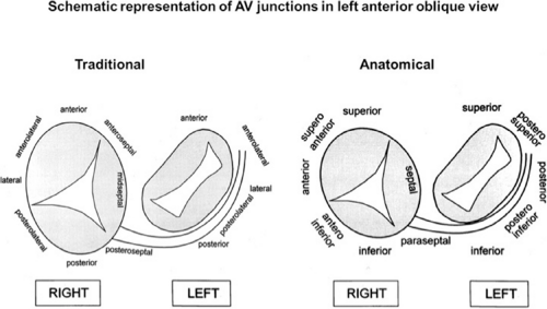 FIGURE 13-9 Schematic representation of the traditional (electrophysiologic) versus true anatomic characterization of bypass tract locations along the A-V annulae. (Adapted from Cosio FG, Anderson RH, Kuck KH, et al. Living anatomy of the atrioventricular junctions. A guide to electrophysiologic mapping. A consensus statement from the cardiac nomenclature study group, working group of arrhythmias, european society of cardiology, and the task force on cardiac nomenclature from NASPE. Circulation 1999;100:e31–e37.) |
Localization of Bypass Tracts
The mapping techniques that are used to localize the origin of the atrial and ventricular insertion sites bypass tracts have been detailed in Chapter 10. Nevertheless, it is important to reiterate that the earliest site of ventricular activation during antegrade pre-excitation and the earliest site of retrograde atrial activation during circus movement tachycardia remain the most important markers for ventricular and atrial insertion sites of the bypass tract, respectively. The presence of bypass tract potentials should be sought and are occasionally present (see Chapter 10, Figs. 10-72 and 10-73). In my opinion, activity recorded from a bypass tract should be recorded as a sharp, narrow spike in both unipolar and bipolar electrograms, and not just as one part of a multicomponent bipolar
signal. Jackman et al.104 have proposed methods of atrial and ventricular stimulations to validate the presence of a bypass tract potential (Figs. 13-10 and 13-11). V-A conduction over a bypass tract with the accessory pathway (AP) potential noted between the ventricular and atrial electrograms is schematically shown in Figure 13-11. V-A block could theoretically be noted either proximal to (loss of potential) or distal to (persistence of a potential) the AP. Proof that this AP is related to the ventricle requires demonstration of the inability of a premature atrial complex to alter the AP. Conversely, if during V-A block the middle potential is absent, the appearance of this potential in response to a premature atrial extrastimulus suggests that the “AP potential” is related to the atrial signal and is not part of ventricular activity.
During pacing-induced antegrade block in the bypass tract (Fig. 13-10), premature stimulation of the ventricle can demonstrate separation of the bypass tract from atrial tissue or a definite association with ventricular tissue. However, unless there is discordance between the results of the AP response to atrial or ventricular stimulation, these responses do not distinguish the AP from a component of either the atrial or ventricular electrogram. Furthermore, since retrograde block is not frequently seen in the bypass tract, the methodology suggested by Jackman et al.104 in Figure 13-11 is not generally applicable. Finally, while AP potentials should appear as sharp spikes, most examples of AP potentials are rarely sharp deflections. In my opinion, the proposed stimulation protocols should only be applied when a sharp spike between atrial ventricular electrograms is present in both unipolar and bipolar recordings. One must remember that the use of filtering of bipolar signals can create a multicomponent electrogram that can be mistaken as a bypass tract. Even the presence of a spike does not necessarily distinguish that signal from one component of a multicomponent atrial or ventricular signal. I personally have never seen an “AP” potential that could be dissociated from both A and V electrogram by these stimulation techniques. Thus, in my opinion most of what have been labeled as AP potentials merely reflect one component of a multicomponent electrogram. Neibauer et al.105 evaluated the criteria proposed by Jackman et al.104 to validate accessory pathway potential (see Chapter 10, Figs. 10-74 and 10-78). They used atrial electrograms that simulated accessory pathway potentials (i.e., atrial electrograms manifesting a split potential separated by at least 30 msec) and assessed the response of these potentials to atrial and ventricular extrastimuli. All but one of the proposed criteria was seen in response to atrial and ventricular stimulations, despite the fact that none of these patients had bypass tracts present. The only observation that they never saw was block between the first and the second component of the atrial electrogram simulating block between the atrium and the bypass tract. This latter observation has never been convincingly demonstrated in our laboratory in any patient with pre-excitation. Although bypass tract recordings can be obtained, and may serve as a marker for catheter ablation of the bypass tract, proof that the electrical signal interpreted as a bypass tract potential is a bypass tract potential, in my opinion, is rarely achieved. More often it is not possible to distinguish a component of the atrial or ventricular electrogram from a true bypass tract potential. In the coronary sinus many, so-called, bypass tract potentials represent signals from muscle sleeves around the coronary sinus.
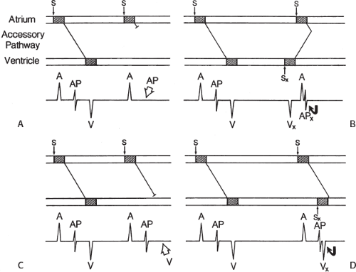 FIGURE 13-10 Use of ventricular stimulation to confirm the presence of a bypass tract potential. On top, atrial pacing produces block in a presumed bypass tract (AP) at the atrial-AP junction (A) and the AP-ventricular junction (C). Ventricular stimulation produces a retrograde AP (B) and demonstrates dissociation with an antegrade AP (D), suggesting that AP is “truly” an AP. S, pacing stimulus; A, atrium; X, premature; V, ventricle. See text for discussion. (From Jackman WM, Friday KJ, Yeung-Lai-Wah JA, et al. New catheter technique for recording left free-wall accessory atrioventricular pathway activation: identification of pathway fiber orientation. Circulation 1988; 78:598.) |
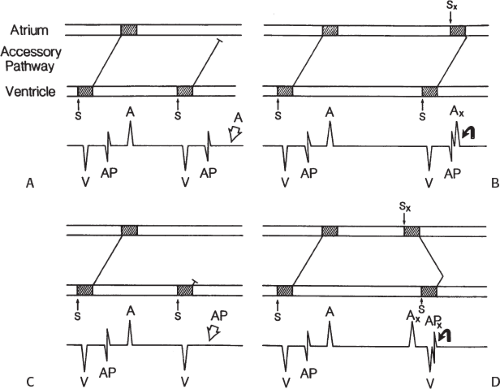 FIGURE 13-11 Use of atrial stimulation to validate the presence of a bypass tract potential in which retrograde block had occurred. On bottom, atrial stimulation is used to confirm that AP is truly an AP. Retrograde block is produced at the AP-atrial junction (A) and the ventricular-AP junction (C). Atrial stimulation does not affect AP (B) and produces an AP (D), allegedly validating the “AP” potential. S, pacing stimulus; X, premature; A, atrium; V, ventricle. See text for discussion. (From Jackman WM, Friday KJ, Yeung-Lai-Wah JA, et al. New catheter technique for recording left free-wall accessory atrioventricular pathway activation: identification of pathway fiber orientation. Circulation 1988;78:598.) |
I do not personally believe the use of an orthogonal electrode enhances one’s ability to record accessory pathway potentials. In contrast to Jackman et al.84,94,104,106,107 I believe that true bypass tract potentials are only recorded in 5% to 15% of patients with pre-excitation syndromes. It is, however, frequent to find abnormal, fragmented atrial signals at sites of early activation during orthodromic tachycardia and ventricular pacing. I think this reflects the marked anisotropic activation in the insertion sites of the bypass tracts or coronary sinus musculature. In our experience, such signals are often associated with the site of earliest activity. It is important to recognize that conduction delays of up to 100 msec or more, including split potentials, may be observed in very small regions of only a few millimeters due to nonuniform anisotropic conduction.108,109,110 Thus, what in some investigator’s opinion is a bypass tract potential, our laboratory would frequently define as the earliest site of atrial activation; hence, in both cases that site would be appropriately ablated by either catheter or surgical technique.
In summary, to validate the presence of an accessory pathway potential, one must be able to dissociate it from both the local atrial and local ventricular electrogram. Most of the examples reporting to demonstrate proof of a bypass tract have not accomplished this. This is also true in some of the examples published attempting to demonstrate the differences between antegrade and retrograde sites of block in accessory pathways during programmed stimulation.111 In my opinion, most electrograms that have been described as accessory pathway potentials represent one component of a fragmented atrial electrogram. Often, the choice of component designated as an accessory pathway potential can vary, depending on whether the investigator is looking at block in the antegrade or retrograde direction. This confusion is readily seen in Figure 13-12 in which the rapid component of a fragmented atrial electrogram is marked as an accessory pathway when block occurs during antegrade stimulation and is considered an atrial deflection during ventricular stimulation.111,112
The multicomponent characteristics of both unipolar and bipolar electrograms recorded during the retrograde conduction of a bypass tract may reflect many factors including (a) fiber orientation of the accessory pathway relative to that of the insertion site in the atrial and ventricular myocardium; (b) the orientation of atrial fibers relative to the recording electrodes (these are usually nearly horizontal at the point of attachment to the annulae); (c) the geometric/spatial relationship of the recording electrode and the site of insertion of the accessory pathway, which is related to; (d) the anatomic location (endocardial vs. epicardial) and physical characteristics (length, width, single trunk vs. “twig-like” insertion) of the bypass tract; and (e) coronary sinus musculature.
More important than trying to decide whether or not a multiple component signal contains an accessory pathway potential is the recognition of the presence of multiple bypass tracts. While this was discussed in Chapter 10, it needs to be reiterated, because a single ablative procedure may fail to cure symptomatic arrhythmias if the presence of an additional bypass tract or another source of arrhythmias, such as A-V nodal reentry, is not diagnosed at the time of the electrophysiology study. Thus, the concept of “single catheter” approaches to ablation of arrhythmias should be abandoned since at least 10% of patients who have multiple arrhythmias and another 10% to 20% (depending on the patient population at the institution performing the
studies) will have multiple bypass tracts. Signs of multiple bypass tracts include:
studies) will have multiple bypass tracts. Signs of multiple bypass tracts include:
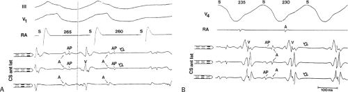 FIGURE 13-12 Example of arbitrary and inconsistent definition of accessory pathway potential. A and B: Purported demonstration of antegrade (A) and retrograde (B) block at the junction of the accessory pathway (AP)-ventricular junction. Close inspection of the electrograms suggests that two components of a fragmented atrial electrogram are arbitrarily labeled AP and A. This is best seen in the middle CS recording in which the slowly inscribed deflection and sharp deflection are called A and AP, respectively, during antegrade block and AP and A, respectively, during retrograde block. (From Kuck KH, Friday KJ, Kunze KP, et al. Sites of conduction block in accessory atrioventricular pathways: basis for concealed accessory pathways. Circulation 1990;82:407.) |
Multiple atrial breakthrough sites during orthodromic tachycardia (Fig. 13-13),
Eccentric atrial activation during circus movement pre-excited tachycardias,
Tachycardia showing fusion between fully pre-excited and narrow QRS complexes, can also be observed with during AVNRT with variable conduction over a bypass tract acting as a bystander,
Different retrograde atrial activation sequences that are present during different tachycardia types (Fig. 13-14),
A mismatch between the earliest site of antegrade ventricular pre-excitation and retrograde atrial activation during circus movement tachycardia, which actually defines multiple pathways, and
The observation of a changing relationship of the His potential to the ventricular electrogram, without any change in the cycle length or atrial activation sequence during a pre-excited tachycardia. This finding suggests the presence of multiple bypass tracts because the His–Purkinje system cannot be a component of the reentrant circuit (Fig. 13-15).
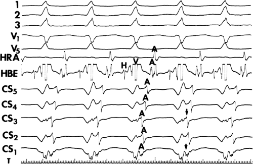 FIGURE 13-13 Multiple bypass tracts recognized by two atrial breakthrough sites. Five surface ECG leads are shown with bipolar, filtered electrograms from the HRA and HBE, and five unipolar (0.05 to 400 Hz) recordings from the CS. CS1 and CS3 show early breakthrough separated by later activation, suggesting two pathways. |
One must also determine whether or not the bypass tract is an innocent bystander during an unrelated arrhythmia. As discussed previously in Chapter 10, atrioventricular, atriofascicular, or nodofascicular bypass tracts may be innocent bystanders during A-V nodal reentry or orthodromic circus
movement tachycardia (see Chapter 10, Figs. 10-32, 10-34, 10-35, 10-132, and 10-136). The presence of dual A-V nodal pathways, with or without A-V nodal reentry, can confound the diagnosis of supraventricular tachyarrhythmias using atrioventricular, atriofascicular, or nodofascicular bypass tracts. This can be seen in Figure 13-16 in which A-V nodal tachycardia can alternate with circus movement tachycardia resulting in variable heart rates and QRS configurations. Detailed analysis of retrograde atrial activation is necessary to delineate both mechanisms so that they may both be appropriately treated during any ablative procedure.
movement tachycardia (see Chapter 10, Figs. 10-32, 10-34, 10-35, 10-132, and 10-136). The presence of dual A-V nodal pathways, with or without A-V nodal reentry, can confound the diagnosis of supraventricular tachyarrhythmias using atrioventricular, atriofascicular, or nodofascicular bypass tracts. This can be seen in Figure 13-16 in which A-V nodal tachycardia can alternate with circus movement tachycardia resulting in variable heart rates and QRS configurations. Detailed analysis of retrograde atrial activation is necessary to delineate both mechanisms so that they may both be appropriately treated during any ablative procedure.
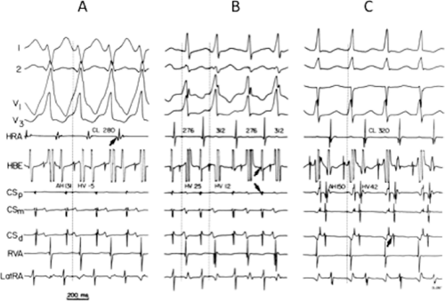 FIGURE 13-14 Multiple bypass tract manifested by fusion during pre-excited tachycardia and different routes of retrograde atrial activation. Three tachycardias are shown. A totally pre-excited tachycardia using a left lateral bypass tract antegradely (A), narrow QRS orthodromic tachycardia (C), and a wide complex tachycardia, which is a fusion of antegrade conduction over a left lateral bypass tract and the A-V node (B). Retrograde atrial activation shows a right anterolateral bypass tract (A), a septal bypass tract (B), and a left lateral bypass tract (C). |
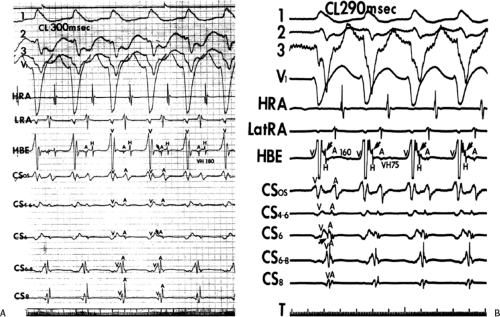 FIGURE 13-15 Pre-excited tachycardia with eccentric atrial activation and changing His bundle activation. A and B: A pre-excited tachycardia is present with retrograde activation over a left posterior free wall bypass tract (retrograde activation earliest in CS site 6). An additional posteroseptal bypass may be present because the atrial activation (A) in the HBE is earlier than the CS os. The His bundle is activated retrogradely by two routes left bundle branch (A) and right bundle branch (B), giving rise to two V-H intervals. The lack of effect of V-H on tachycardia cycle length suggests no role for the normal A-V conducting system in the tachycardia. CL, cycle length; LRA, low right atrium. |
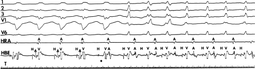 FIGURE 13-16 A-V nodal reentry alternating with orthodromic circus movement tachycardia. A-V nodal reentry with LBBE aberration is present for the first four complexes. On the fifth complex (asterisk), retrograde block in the fast pathway terminates A-V nodal reentry, but the tachycardia continues as circus movement tachycardia, using a right lateral bypass tract. Phase 3 block in the RBE occurs at the onset of circus movement tachycardia. |
The presence of dual A-V nodal pathways, without A-V nodal reentry due to the absence of retrograde fast pathway conduction, can cause a change in cycle length of circus movement tachycardia. This may occur as an alternation of the tachycardia cycle length or two distinct tachycardia cycle lengths, depending on the route of antegrade conduction over the A-V node. Conduction over the slow A-V nodal pathway during orthodromic tachycardia can result in antegrade conduction over an additional innocent bystander atriofascicular or nodofascicular bypass tract. Thus, activation of the ventricle over an atriofascicular or nodofascicular bypass tract during orthodromic tachycardia can occur. The orthodromic tachycardia may only be recognized when antegrade conduction proceeds over the fast pathway. This latter situation is demonstrated in Figure 13-17, in which an atriofascicular bypass tract functions passively to produce an apparent atriofascicular circus movement tachycardia when antegrade conduction uses a slow A-V nodal pathway. A change from the atriofascicular “QRS complex” to a narrow complex circus movement tachycardia was produced by a VPC, which shifted antegrade A-V nodal conduction from slow to fast pathway. This could produce retrograde concealment into the atriofascicular pathway at the same time. The narrow complex circus movement tachycardia demonstrated antegrade conduction over the faster A-V nodal pathway
with retrograde conduction over a slowly conducting left lateral bypass tract. Alternatively one could suggest that this is a nodofascicular pathway arising from the slow A-V nodal pathway. In this instance the VPC would change the QRS complex solely due to the shift to “fast pathway” conduction due to a marked delay in retrograde atrial conduction over the slowly conducting left lateral bypass tract. The longer A-A interval allows the fast pathway to recover. The His timing from the onset of ventricular activation to the right bundle potential is much shorter during the “Mahaim” tachycardia (V-RB = 10 msec) than during the VPD delivered at the right ventricular apex (V-RB = 65 msec) suggesting a close physical relationship of the origin of the Mahaim fiber to the proximal right bundle branch. In this instance, during sinus rhythm right atrial pacing produced pre-excitation and left atrial pacing did not, confirming the presence of an atriofascicular pathway at the anterolateral tricuspid annulus. Thus, a systematic approach must be undertaken to delineate the necessary components of reentrant tachycardias so that catheter-based or surgical ablative procedures will not destroy tissues unrelated to the tachyarrhythmia, leading to unnecessary adverse, long-term sequelae.
with retrograde conduction over a slowly conducting left lateral bypass tract. Alternatively one could suggest that this is a nodofascicular pathway arising from the slow A-V nodal pathway. In this instance the VPC would change the QRS complex solely due to the shift to “fast pathway” conduction due to a marked delay in retrograde atrial conduction over the slowly conducting left lateral bypass tract. The longer A-A interval allows the fast pathway to recover. The His timing from the onset of ventricular activation to the right bundle potential is much shorter during the “Mahaim” tachycardia (V-RB = 10 msec) than during the VPD delivered at the right ventricular apex (V-RB = 65 msec) suggesting a close physical relationship of the origin of the Mahaim fiber to the proximal right bundle branch. In this instance, during sinus rhythm right atrial pacing produced pre-excitation and left atrial pacing did not, confirming the presence of an atriofascicular pathway at the anterolateral tricuspid annulus. Thus, a systematic approach must be undertaken to delineate the necessary components of reentrant tachycardias so that catheter-based or surgical ablative procedures will not destroy tissues unrelated to the tachyarrhythmia, leading to unnecessary adverse, long-term sequelae.
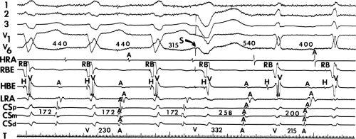 FIGURE 13-17 Atriofasicular reentry during circus movement tachycardia. Five ECG leads are shown with electrograms from the HRA, right bundle (RBE), HBE, lateral right atrium (LRA), and proximal, mid- and distal coronary sinus (CS, at lateral left atrium). Antegrade conduction initially occurs over an atriofasicular bypass tract (note RB precedes H), and retrograde conduction over a slowly conducting left lateral bypass tract. A VPC penetrates the A-V node, shifting conduction to a fast A-V nodal pathway and the tachycardia continues as a narrow QRS. See text for discussion. |
Catheter Ablation of Bypass Tracts
The indications for catheter ablation of bypass tracts have been markedly liberalized with the development and refinement of catheter technology and newer mapping data acquisition systems, both of which have led to an extremely high success rate for curing arrhythmias associated with bypass tracts. Multicenter experience reports acute success rates averaging 95% with a recurrence rate of 3% to 10%.113,114,115,116,117 More importantly, cost-effectiveness of this procedure has been established.118 As such, virtually all patients with symptomatic arrhythmias due to accessory pathways should undergo catheter ablation as a primary therapy. However, as stated in Chapter 10, I do not believe that the asymptomatic patient with manifest pre-excitation, regardless of the refractory period of the bypass tract or the ventricular response during induced atrial fibrillation, should undergo ablation. This concept has been recently reviewed in the literature.119,120,121,122 There is no evidence that such patients develop life-threatening arrhythmias. For patients with symptomatic arrhythmias due to accessory pathways RF, catheter ablation, with its high success rate and low morbidity, is the standard of care.
Ablation of bypass tracts may be accomplished using an atrial or ventricular approach, as schematically depicted in Figure 13-18. Simultaneous recordings from both approaches are shown in Figure 13-19. In our laboratory, we prefer a left ventricular approach for left-sided bypass tracts and a right atrial approach for right-sided and septal bypass tracts. A transseptal approach for ablating left-sided bypass tracts on the atrial side has also been used and shown to be equally effective to the retrograde aortic approach.123,124 We use a retrograde aortic approach to the left ventricular approach in order to avoid the potential complications of transseptal catheterization. Severe aortic or femoral atherosclerotic disease would be another indication for a transseptal approach. Others prefer a transseptal approach for all left-sided bypass tracts. In my experience, contact and stability are generally better with a retrograde approach and ablation on the ventricular side of the mitral annulus. As such, the power needed to achieve adequate temperatures or impedance changes is less using the retrograde approach than during a transseptal approach. I believe this decreases the incidence of coagulum formation and potential for stroke. Left posteroseptal bypass tracts can be ablated from either the left ventricle or transseptal left atrium at the medial aspect of the mitral annulus, but in my opinion, the retrograde approach is easier. Finally, some cases of posteroseptal bypass tracts, particularly those that are epicardial and that are associated with abnormality in the coronary sinus (e.g., coronary sinus diverticulum) must be ablated from within the coronary sinus. In the presence of overt pre-excitation, an epicardial location of the bypass tract is suggested if the earliest site of endocardial ventricular activation does not precede the onset of the delta wave. In my experience, such bypass tracts are almost always in the left posterior paraseptal space or associated with a coronary vein in which the bypass tract is located.
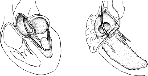 FIGURE 13-18 Methods of catheter ablation of bypass tracts. Ablation of left-sided bypass tracts is most commonly performed from a ventricular approach in which the electrode through which energy is delivered is placed at the mitral annulus under the mitral valve. (Left) For right-sided bypass tracts, we use an atrial approach with the ablating electrode placed on the A-V ring. (Right) A guiding mapping catheter in the right coronary artery has been suggested by some. |
Left-sided bypass tracts (manifest or concealed) are the most common types of atrioventricular bypass tracts. They make up approximately 60% of all bypass tracts that we have studied. Regardless of whether a transseptal or a retrograde aortic left ventricular approach is used, an initial attempt at localization is made using a multipolar coronary sinus catheter. The recordings from the coronary sinus catheter are usually made in the bipolar configuration, but it is often helpful to include unipolar as well as bipolar signals. Unipolar signals are used to more precisely localize the sites of atrial or ventricular insertion of the bypass tract. In the coronary sinus, an atrial or ventricular unipolar electrogram with a QS complex demonstrating a rapid intrinsicoid deflection
is believed to represent the site of insertion of an epicardially positioned bypass tract (Fig. 13-20). A ventricular electrogram with an rS morphology recorded from the coronary sinus may be the earliest activation of an endocardially located bypass tract.93,125 Alternatively, the rS may represent a recording that is somewhat removed from the site of atrial and/or ventricular insertion. Both atrial and ventricular components may exhibit normal smooth contours or may be polyphasic or fragmented. Fragmentation of unipolar signals is always associated with fragmented bipolar signals and, in my opinion, reflects either anisotropic conduction from the site of insertion of the bypass tract or potentials from the CS musculature, or both. Examples of QS and rS atrial signals, which are smooth or fragmented, are demonstrated earlier in Figure 13-13. Use of unipolar signals is also critical in order to demonstrate that the distal electrode, which is used for RF delivery, is actually the electrode recording the earliest activity. If only bipolar recordings are utilized, one does not know which of the two poles is responsible for the earliest component of the bipolar electrogram. Figure 13-21 demonstrates how the use of unipolar electrograms demonstrates that the second (proximal) pole of the distal bipolar electrogram was responsible for the earliest activity in that bipolar electrogram. Delivery of RF energy at this site through unipolar lead 1 would not have resulted in elimination of the bypass tract. Thus, the use of unipolar electrograms cannot be overstated. They provide directional information and importantly provide critical information that is necessary to demonstrate that the distal pole through which the RF energy is delivered is at the site of earliest activation. This is true regardless of whether one is accessing the earliest site of ventricular activation in a pre-excited complex or the earliest atrial activation during retrograde activation over the bypass tracts.
is believed to represent the site of insertion of an epicardially positioned bypass tract (Fig. 13-20). A ventricular electrogram with an rS morphology recorded from the coronary sinus may be the earliest activation of an endocardially located bypass tract.93,125 Alternatively, the rS may represent a recording that is somewhat removed from the site of atrial and/or ventricular insertion. Both atrial and ventricular components may exhibit normal smooth contours or may be polyphasic or fragmented. Fragmentation of unipolar signals is always associated with fragmented bipolar signals and, in my opinion, reflects either anisotropic conduction from the site of insertion of the bypass tract or potentials from the CS musculature, or both. Examples of QS and rS atrial signals, which are smooth or fragmented, are demonstrated earlier in Figure 13-13. Use of unipolar signals is also critical in order to demonstrate that the distal electrode, which is used for RF delivery, is actually the electrode recording the earliest activity. If only bipolar recordings are utilized, one does not know which of the two poles is responsible for the earliest component of the bipolar electrogram. Figure 13-21 demonstrates how the use of unipolar electrograms demonstrates that the second (proximal) pole of the distal bipolar electrogram was responsible for the earliest activity in that bipolar electrogram. Delivery of RF energy at this site through unipolar lead 1 would not have resulted in elimination of the bypass tract. Thus, the use of unipolar electrograms cannot be overstated. They provide directional information and importantly provide critical information that is necessary to demonstrate that the distal pole through which the RF energy is delivered is at the site of earliest activation. This is true regardless of whether one is accessing the earliest site of ventricular activation in a pre-excited complex or the earliest atrial activation during retrograde activation over the bypass tracts.
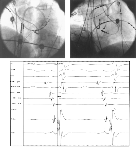 FIGURE 13-19 Atrial (transseptal) and ventricular (retrograde aortic) approaches to the ablation of left posterior bypass tract. Left anterior oblique (left) and right anterior oblique (right) are shown with analog recordings of atrial and ventricular activation at the site of earliest ventricular activation recorded from either the left atrium or left ventricle (bottom). Both demonstrate ventricular activation prior to the delta wave, but the ventricular electrogram recorded from the left ventricle begins slightly earlier than that recorded from the left atrium. |
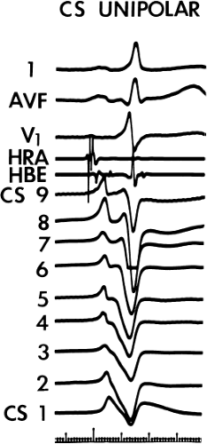 FIGURE 13-20 Unipolar electrograms from the coronary sinus in a patient with a left-sided bypass tract. Nine unipolar electrograms from a decapolar catheter are shown with ECG leads and electrograms from the HRA and HBE. Pole 2 shows the earliest intrinsicoid deflection. Note the P-QS configuration. See text for discussion. |
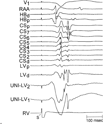 FIGURE 13-21 Use of unipolar recordings to demonstrate the source of the different components of a bipolar electrogram. Surface ECG lead V1 is shown with electrograms from the right atrial appendage (RAA), His bundle (HB), and eight electrograms from the proximal (p) to distal (d) coronary sinus (CS). Left ventricular distal and proximal bipolar electrograms are shown following that, and underneath that, unipolar signals from the distal electrode and second pole. The left ventricular distal electrogram shows the earliest recorded atrial activity during ventricular pacing. The atrial electrogram is made up of two components. Using the unipolar signals, one can see that the second pole (LV2) is responsible for the earliest component of the distal LV electrogram while the tip electrode is responsible for the second component. This suggests that this is an inappropriate site for ablation since the tip electrode was not recording from the site of earliest atrial activation. See text for discussion. |
There are additional features in the coronary
sinus recordings that should make one expect an epicardial location requiring manipulation of the catheter down one of the cardiac veins. First is the appearance of the early, near-simultaneous activation along at least three bipolar pairs of the coronary sinus catheter. This suggests that the coronary sinus is removed from the site of earliest activation from which radial spread approaches the coronary sinus catheter in a broad wavefront and that the coronary sinus is remote from the mitral annulus. In such an instance, one should attempt to manipulate catheters in various cardiac veins in an attempt to find earlier activity (Fig. 13-22). Manipulating the catheter in the cardiac vein located an early potential 3 cm down the vein closer to the mitral annulus and the ventricular epicardium. Delivery of RF energy at this site resulted in block in the bypass tract (Fig. 13-23). These pathways are also able to
be ablated by the retrograde approach in which a catheter can be placed at the mitral annulus. In this case ablation can be performed without concern of perforating the coronary sinus. Another important observation shown in this tracing is the finding of a local V-A time exceeding 50 msec in the coronary sinus in the presence of a rapidly conducting bypass tract. Even if the earliest CS recording is bracketed, as shown in Figure 13-24, this long, local V-A time at the earliest site suggests that exploration of a cardiac vein be undertaken and that the coronary sinus is far away from the site of earliest activation. Unipolar electrograms from the electrodes surrounding the early bipolar sites usually show a small R wave (Fig. 13-24). Exploration of the cardiac vein proximal to CS bipolar pair 3 yielded an earlier atrial electrogram with a V-A interval of 30 msec at a site adjacent to the mitral annulus. This electrogram preceded the earliest recorded in the coronary sinus by 35 msec. Successful ablation of the bypass tract was accomplished at this site.
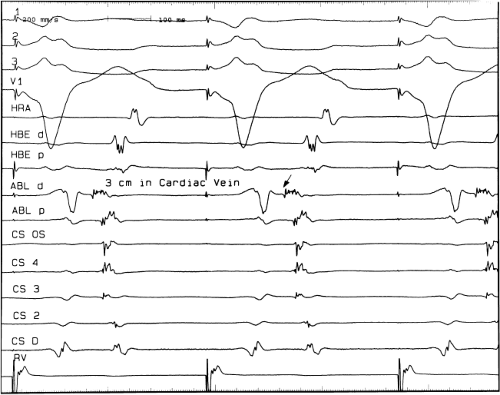 FIGURE 13-22 Simultaneous activation of multiple electrodes in the coronary sinus suggesting it is removed from the mitral annulus. Surface leads I, II, III, and V1 are shown during ventricular pacing. Electrograms from the HRA, the distal and proximal HBE, the distal and proximal ablation (ABL catheter) located 3 cm inside the cardiac drain and electrograms from the coronary sinus OS, the fourth bipolar pair, third bipolar pair, second bipolar pair, and distal pair and the RV. Activation in poles 3, 4, and the os of the coronary sinus showed nearly simultaneous onset of activation. This suggested that the coronary sinus was removed from the mitral annulus. As a result, a catheter was placed 3 cm in a posterior cardiac vein, at which point the mitral annulus was approximated. At this site the earliest atrial activation was recorded, 35 msec prior to that in the coronary sinus. See text for discussion. |
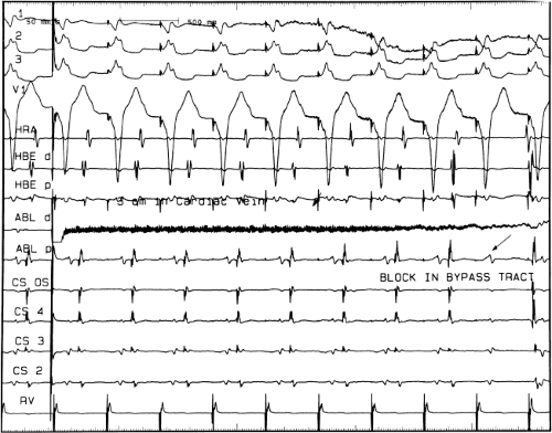 FIGURE 13-23 Ablation of concealed bypass tract in a posterior cardiac vein 3 cm from the os of the coronary sinus. This is the same patient as recorded in Figure 13-16 in whom earliest activation was recorded in a cardiac vein. Ablation in that cardiac vein during ventricular pacing resulted in block in the bypass tract in less than 3 seconds (see arrow). |
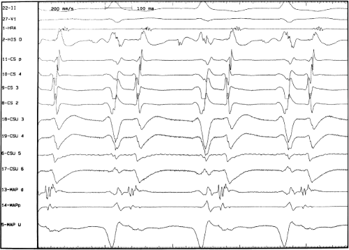 FIGURE 13-24 Local coronary sinus with V-A conduction times exceeding 50 msec suggest the presence of a bypass tract removed from the coronary sinus. In this figure, during circus movement tachycardia bipolar recordings are shown from four coronary sinus pairs (CS2-CSP) and unipolar coronary sinus recordings from poles 2 to 6. These poles were chosen since the earliest bipolar recording was in CS3 (poles 5 and 6). The earliest activation time locally was nearly 75 msec in pole 5, which had a small R-deep S wave. This suggested that the coronary sinus was removed from the mitral annulus and earliest site. A catheter (mapd) inserted in the vein proximate to pole 3 revealed the earliest bipolar and unipolar recording some 30 msec at the head of the earliest bipolar recording (in the coronary sinus). This was the target site for successful ablation. See text for discussion. |
If at all possible, ablation should be carried out in sinus rhythm or preferably during atrial or ventricular pacing. Application of RF energy during a tachycardia is often associated with catheter instability, particularly if there is abrupt loss of conduction over the bypass tract. Block in a bypass tract results in immediate termination of the tachycardia, which is often associated with displacement of the catheter from its critical position. Since there will be no conduction for a variable period of time one cannot find a suitable target to complete the RF lesion. One can only hope for return of conduction over the bypass tract in a short period of time so that it can again be targeted. Unfortunately, on some occasions the bypass tract conduction will not return until the patient leaves the hospital and the tachycardia recurs. Ablation during continuous ventricular pacing either during sinus rhythm (as long as eccentric activation is seen) or while entraining the SVT prevents this problem. Use of mapping system may obviate this problem by tagging the initial site of ablation, allowing the investigator to return with great precision to that site.
Selection of a good site during ventricular pacing may sometimes be difficult because of diminution of the amplitude of the atrial electrogram and merging of the atrial electrogram with the ventricular electrogram because of the influence of slanted bypass tracts. Rapid ventricular pacing to produce V-A block can demonstrate what component of the ablation electrogram is ventricular and what is atrial (Fig. 13-25). Another maneuver is to alternatively pace the atrium and ventricle and the ventricle separately (Fig. 13-26). In this way, V-A conduction over the bypass tract will only be evident with ventricular pacing only; electrograms present only during ventricular pacing represent atrial activity. As mentioned above, as well as in Chapter 10, bypass tracts are frequently slanted (see Figs. 10-48 and 10-49).126,127 If one uses a ventricular approach to ablate a concealed bypass tract, the ventricular insertion site can be identified as that site that maintains a constant V-A interval on the mapping catheter, despite differences in the direction of activation to the ventricular site and differences in the coronary sinus recordings. This is schematically shown in Figure 13-27. The local V-A time measured on the ablation catheter must remain constant if activation occurs over the bypass tract, regardless of which direction the ventricular wavefront engaging a bypass tract is traveling. Sites that may have a shorter V-A interval in response to retrograde conduction over bypass tract activation during a ventricular activation from one direction may have a markedly different V-A
interval when the ventricle and bypass tract are activated in the opposite direction.
interval when the ventricle and bypass tract are activated in the opposite direction.
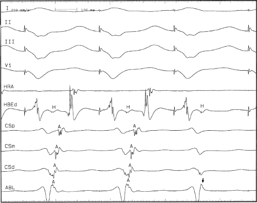 FIGURE 13-25 Use of rapid ventricular pacing to ascertain where the atrial deflection is located during circus movement tachycardia or ventricular pacing. Ventricular pacing with a cycle length of 350 msec is shown with surface lead II, III, and V1 and recordings from the HRA, HBE 3, CS leads and an ablation catheter. The first two pace complexes are a search of the atrial deflections, the beginning of which are hard to see in the distal coronary sinus and the ablation catheter. This third ventricular paced complex is not associated with atrial electrograms and allows one to see where the atrial electrogram began. V-A block during rapid pacing is therefore a good method to assess the exact location of atrial activity during circus movement tachycardia or ventricular pacing. See text for discussion. |
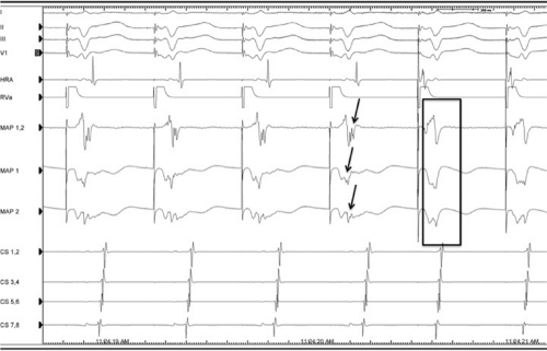 FIGURE 13-26 Use of differential atrial and ventricular pacing to understand the onset of the atrial electrogram. Three surface leads and intracardiac recordings from the HRA, RV, mapping catheter (MAP 1,2 bipolar recording, MAP1 and MAP, unipolar recordings) and CS are shown in a patient with a right-sided accessory pathway during ventricular pacing (left) and simultaneous atrial and ventricular pacing (right). Simultaneous pacing captures the local atrial electrogram; its absence helps to determine the onset of the atrial activation during ventricular pacing (arrows). (Courtesy of Peter Low, MD.) |
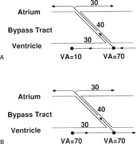 FIGURE 13-27 Locating the ventricular site of insertion of a concealed bypass tract. A bypass tract is shown to connect the atrium and ventricle at an angle. The effect of a paced wavefront from right to left (A) and left to right (B) on local V-A times is shown. The ventricular site of insertion should have a constant (V-A) interval regardless of the direction of activation. See text for discussion. |
Using the ventricular approach the catheter is positioned just underneath the mitral annulus as depicted in Figures 13-18 and 13-19, to record a ventricular electrogram and an atrial electrogram. At the appropriate position (near the ventricular insertion site) the atrial deflection is usually one-fourth the size of the ventricular deflection and during ventricular pacing the atrial deflection gets even smaller and sometimes becomes lost in the ventricular electrogram. The maneuvers discussed above can help define the onset of atrial activation during conduction over the bypass tract. During ventricular pacing, retrograde atrial activation is usually earlier than that recorded in the coronary sinus. Once this site is recorded and is stable, RF is delivered during ventricular pacing (Fig. 13-28).
During antegrade pre-excitation the site of earliest ventricular activation usually precedes the delta waves by 10 to 30 msec and is associated with a QS or rS morphology depending on whether it is endocardial, intramural, or subepicardial in location. In rare cases, a left lateral bypass tract with a long A-V conduction time (which may or may not be decremental) is present. In such cases, no overt pre-excitation is obvious in sinus rhythm, but may only be manifest by pacing at the left atrium or via the coronary sinus. In such cases, successful ablation of the bypass tract may cause a change of the mid or terminal components of the QRS, which is associated with an abrupt increase in the local A-V interval at the site of the bypass tract (Fig. 13-29).
When using the ventricular approach, because the contact is usually good, we aim for a temperature of 55° to 65°C with temperature control catheters, or the lowest power, which results in a 10-Ω drop in lead impedance. This is typically easily achievable. If one is at the appropriate site, loss of conduction over the bypass tract is accomplished in less than 10 seconds (Figs. 13-30 and 13-31). If the transseptal approach is used, catheter stability is not as reliable, and a sheath is invariably required to maintain stable contact. The sheath is usually positioned in the lateral left atrium through which the catheter is passed toward the medial aspect of the mitral annulus. The catheter can then be withdrawn slowly to map the mitral annulus until the earliest retrograde atrial activation is recorded during the tachycardia or ventricular pacing. Achievement of appropriate temperatures, or, more importantly, drops in impedance are more difficult from the transseptal approach due to the loss of temperature via convective cooling of the blood. Finally, if the ablation is carried out within the coronary sinus, and a standard 4- to 5-mm tip catheter is used, I recommend keeping temperatures ≤55°C, and use impedance drops to determine how much energy is delivered. I generally use the lowest energy, which results in a 10-Ω drop in impedance, regardless of the temperature. Use of a cool-tip catheter decreases the risk of char and, as stated above, temperature cannot be used and a decrease in impedance demonstrates effective energy delivery. Usually, epicardial pathways are eliminated quickly, but I try to maintain delivery of energy for a minute since I believe many of these bypass tracts insert as multiple twigs or broad bands in the muscular sheath of the coronary vein. Using such precautions, ablation from within the coronary sinus appears safe,128 although I usually attempt ablation from the LV or LA first. The safety parameters of ablation in the CS using larger tip (8 to 10 mm) or cool-tip catheters are not known, but experimental studies and clinical experiences have demonstrated some potential for inadvertent damage to adjacent coronary arteries.129
For ablation of bypass tracts located around the tricuspid annulus, one may need to use a superior vena cava approach. The vast majority of bypass tracts around the tricuspid valve can be reached through catheters introduced via the inferior vena cava, although occasionally the catheter must be placed via the superior vena cava when the bypass tract is located inferolaterally (i.e., inferoanterior). As stated earlier in the chapter, although some investigators have suggested using a small catheter placed in the right coronary artery to guide mapping of right-sided bypass tracts, we believe this should not be done routinely and that regionalization of the bypass tract can be readily accomplished using a Halo catheter or a multipolar catheter positioned around the tricuspid annulus. When pre-excitation is present, the earliest onset of ventricular activation recorded on the ablation catheter should precede the delta wave by at least 25 msec using either unipolar or bipolar electrograms. Examples of mapping and ablation of a right anterior manifest, anterogradely conducting and a concealed right lateral bypass tract
are shown in Figure 13-32. Sheaths are available and helpful for the stabilization of catheters positioned inferolaterally along the tricuspid annulus. Folding over of the atrial myocardium around the annulus is associated with bypass tracts that may insert into the atrium 1 cm from the annulus. This can lead to ablation failures if not appreciated. Posteroseptal bypass tracts, which are actually the second most common, usually can be readily approached in the inferior septal regions of the tricuspid annulus. This name is actually a misnomer, since they are not truly “septal,” but inferoposterior to the true atrial septum, which ends in the His–A-V node area, at the central fibrous trigone. The atrial insertion site may involve the proximal portions of the CS, but most of these bypass tracts can be approached from the right atrium. Approximately 25% will require ablation in the os or proximal coronary sinus. These can be suspected when delta waves are negative in leads 2 and 3 or when the retrograde atrial activation shows equal negativity of P waves in II and III and aVF. Midseptal pathways are those that are found between the os of the CS and the His. These are truly septal and may be approached from either the right side or on rare occasions from the left side and are associated with a 5% incidence of heart block if the catheter is positioned in the triangle of Koch. Such bypass tracts should be ablated with the catheter on the tricuspid annulus or on the ventricular side of the tricuspid annulus to decrease the incidence of A-V block. Safety will further be enhanced by using the lowest power required to get an impedance drop of 10 Ω. The anterior septal pathways are hard to distinguish from pathways that are para-Hisian, but both insert into the RV and are really superior paraseptal. They often exhibit a bypass tract potential and/or early activation at a site without a His bundle deflection (Fig. 13-33). The para-Hisian pathways, by definition, are recorded with simultaneous His bundle activity from which it needs to be distinguished. An ablation of the para-Hisian pathway is shown in Figure 13-34. In this particular instance the ablation catheter was positioned so that the tip produced pressure perpendicularly to the His bundle region. This led to a rather slowly inscribed ventricular depolarization consistent with the onset of ventricular activity as well as a slowly inscribed “inferior” His bundle deflection, which times identically with the discrete bipolar deflection on the His bundle catheter. With the loss of pre-excitation there is loss of the negative deflection between the A and the broad H and disappearance of the delta wave. These fibers are very superficial and protected by a fibrous sheath, so with use of low power and temperatures not exceeding 52°C the risk of permanent heart block is less than 1%. Right bundle branch block (RBBB) is a frequent complication of ablation of para-Hisian pathways (particularly if ablation is performed on the ventricular side of the annulus) since the right bundle is often injured as it emerges from the central fibrous trigone.
Catheter positions for left lateral (posterior), right inferior paraseptal and right anterior bypass tracts are shown in Figures 13-35 to 13-37.
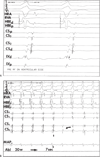 FIGURE 13-28 Ventricular approach to mapping and ablation of a concealed bypass tract. Surface ECG leads I, II, III, V1, and electrograms from the HRA, HBE, 4, CS recordings and left ventricular mapping recordings from the ablation catheter are shown. In (A), during ventricular pacing, the earliest activity recorded in the left ventricular mapping catheter was seen to be opposite the recording in the distal CS. Note the small atrial deflection which is 30 msec earlier than the earliest recording in the CS. Rapid ventricular pacing is often necessary to discern the onset of atrial activity (Fig. 13-25). In (B) application of RF energy during pacing produces loss of activation over the bypass tract and atrioventricular dissociation after 7 seconds. |
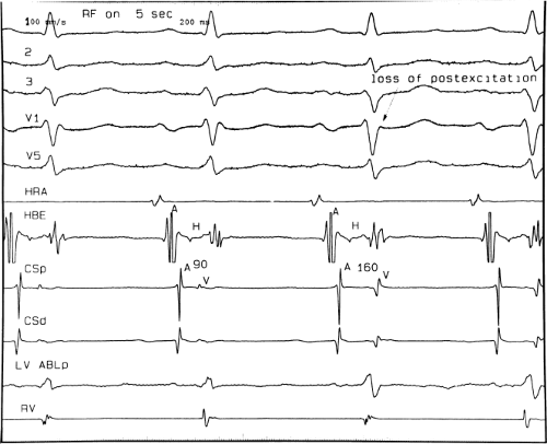 FIGURE 13-29 Effect of ablation of a bypass tract with “post excitation.” ECG leads I, II, III, V1, and V5 are shown with electrograms from the HRA, HBE, CS, and left ventricular ablation catheter and RV. A left lateral bypass tract is present with a long conduction time, which was associated with a local A-V interval of 90 msec. No overt pre-excitation is present because the area of the ventricle that is “pre-excited” occurs after the onset of normal activation. With radiofrequency application one can see a loss of the terminal forces in the QRS and a lengthening of the local A-V interval. Thus, successful ablation of an antegradely conducting bypass tract with a long conduction time may produce changes in the mid and terminal parts of the QRS since a delta wave may not be seen. See text for discussion. |
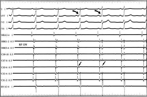 FIGURE 13-30 Ablation of left lateral bypass tract from the sinus rhythm. Surface ECG leads I, AVF, V2, and V6 are shown with intracardiac recordings. The earliest site of ventricular activation is opposite CS bipolar electrogram 5 to 6. Radiofrequency energy abolishes antegrade conduction over the bypass tract (arrows), which is clearly seen on both the surface ECG and the intracardiac recording from CS5–6. |
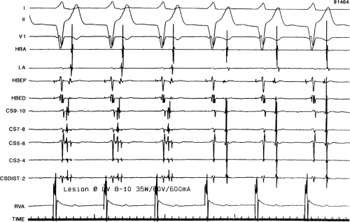 FIGURE 13-31 Radiofrequency ablation of a retrogradely conducting concealed left lateral bypass tract. RF energy is delivered during ventricular pacing in a patient with a concealed left-sided bypass tract. The earliest atrial activation is recorded with the ventricular approach opposite CS 5 to 6 during ventricular pacing. Note the remarkable fractionation in the CS electrograms. There is an abrupt block of retrograde conduction in the bypass tract 4 seconds after the onset of 35 W of RF energy. |
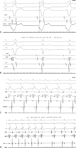 FIGURE 13-32 Radiofrequency ablation of right-sided bypass tracts. A and B: Ventricular pre-excitation is recorded from a unipolar rove electrode as an intrinsicoid deflection 25 msec before the delta wave during sinus rhythm. RF energy delivered at this site abruptly causes loss of pre-excitation over this anteroseptal bypass tract. C and D: SVT using a right anterolateral bypass tract is present (C). The RF rove catheter records earliest bipolar activity on the atrial side of the tricuspid valve. RF energy delivered during SVT produces block in the bypass tract with immediate return to sinus rhythm and no evidence of pre-excitation. |
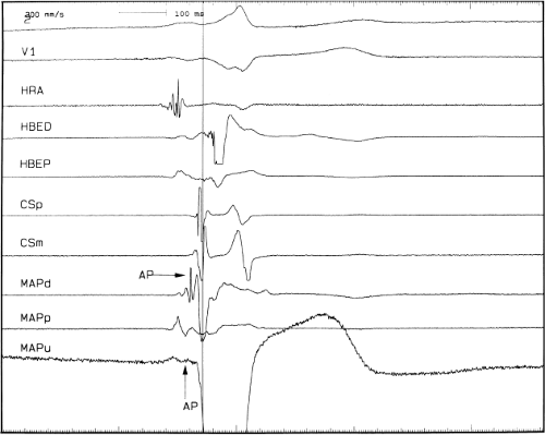 FIGURE 13-33 Anteroseptal bypass tract. Anteroseptal bypass tracts are characterized by the presence of a bypass tract potential and the absence of a His bundle potential in the apex of the triangle of Koch. Note that the mapping catheter (MAPD) has an accessory pathway potential in the bipolar and perhaps in the unipolar (MAPU) recordings. Note that the HBE does not show a clear His deflection. See text for discussion. |
Our overall success rate for ablation of all pathways is 97%. The most difficult for me have been the right free wall pathways, particularly if approached from the inferior vena cava. This is due to both poor contact and the fact that these bypass tracts are often off the annulus, crossing through a “folded” right atrium over the ventricle. An SVC approach and/or use of sheaths for stabilization are often required for success. In the last 10 years we have had only four failures. One was a left epicardial bypass tract, which actually disappeared within 3 seconds of RF ablation. The RF energy was delivered for 15 seconds and then discontinued because of pain. The
procedure was terminated at that time at the patient’s request. Bypass tract conduction returned several hours later. The second failure was in an intermediate pathway. Initial attempts at ablation from the right side produced transient success but the arrhythmia recurred 6 hours later. On the following day a second ablation was successful using the retrograde aortic approach. The third was right free wall pathway that disappeared in 10 seconds after the onset of ablation, only to recover 2 weeks later; repeat ablation resulted in subsequent durable success. The fourth was in right-sided accessory pathway in a patient with Ebstein anomaly. Bypass tract conduction blocked in less than 10 seconds with ablation, but recurred within 2 weeks; a recurrent ablation attempt resulted in the same sequence of events. At surgery, a 1.5-cm wide A-V band was observed with scar from RF lesion delivery in the center. Extensive cryoablation was performed but pathway conduction and SVT returned by 1 month.
procedure was terminated at that time at the patient’s request. Bypass tract conduction returned several hours later. The second failure was in an intermediate pathway. Initial attempts at ablation from the right side produced transient success but the arrhythmia recurred 6 hours later. On the following day a second ablation was successful using the retrograde aortic approach. The third was right free wall pathway that disappeared in 10 seconds after the onset of ablation, only to recover 2 weeks later; repeat ablation resulted in subsequent durable success. The fourth was in right-sided accessory pathway in a patient with Ebstein anomaly. Bypass tract conduction blocked in less than 10 seconds with ablation, but recurred within 2 weeks; a recurrent ablation attempt resulted in the same sequence of events. At surgery, a 1.5-cm wide A-V band was observed with scar from RF lesion delivery in the center. Extensive cryoablation was performed but pathway conduction and SVT returned by 1 month.
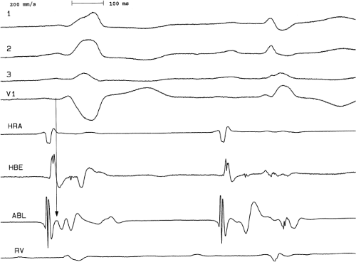 FIGURE 13-34 Para-Hisian bypass tract. This tracing compares the electrograms recorded in the His bundle recording and the ablation catheter before (left) and after (right) catheter pressure caused temporary bypass tract block. The ABL electrogram recording shows a slowly inscribed potential at the onset of ventricular activation (arrow) which is simultaneous with a similar deflection in the His catheter recording (which represents activation over the bypass tract). There is a similar slowly inscribed potential in the ABL signal that is simultaneous with His activation. This is validated with loss of pre-excitation demonstrating consistent positioning of the His bundle potential associated with the slowly inscribed second potential in the first complex and loss of the pre-excitation in the first negative potential in the first complex. Right bundle branch block is present, which facilitates the observation of a broad slowly inscribed His deflection from the ventricular myocardium. See text for discussion. |
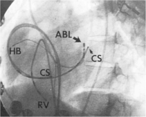 FIGURE 13-35 Catheter position for left-sided bypass tract ablation. Two catheters are placed in the CS (one at the os and the other at the lateral wall). An RV catheter and a His bundle (HB) catheter are also shown. The (ABL) catheter was passed retrogradely to the LV, and the tip (large arrow) was placed opposite the distal pole of the CS catheter, from which the earliest retrograde activity was recorded (small arrow). |
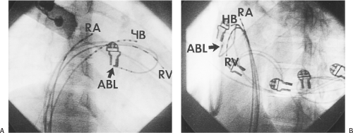 FIGURE 13-36 Catheter position for the ablation of a right inferior paraseptal bypass tract. A: A right anterior oblique (RAO) view is shown in which the ablation (ABL) catheter is looped in the right atrium (RA) and positioned at the ventricular side of the A-V ring (arrow, ABL). B: A left anterior oblique (LAO) view of the same catheter is shown (arrow, ABL). Quadripolar catheters are also seen in the RA and RV as well as a decapolar catheter in the His bundle-A-V junction catheter. |
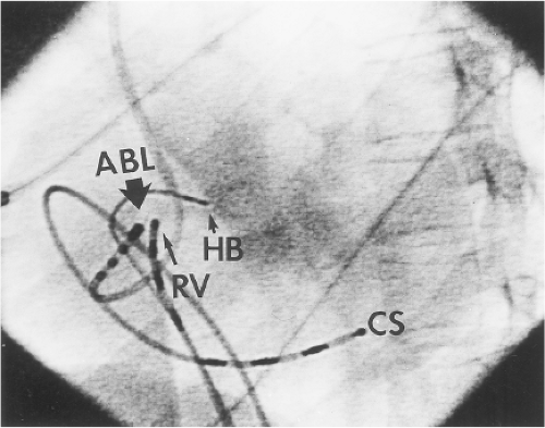 FIGURE 13-37 Catheter position for ablation of a right anterior bypass tract. Catheters are shown in the 45-degree LAO view. The His bundle catheter (small arrow, HB) is medial to the ablation catheter (ABL, heavy solid arrow), which is on the atrial side of the anterolateral aspect of the tricuspid valve. A roving catheter is placed just across the valve in the RV adjacent to the ABL catheter (thin arrow). |
In general, the greater the experience of the operator, the higher the success rate and the fewer lesions used. While success rates in many laboratories exceed 95%, the use of multisite “insurance lesions” to achieve these results should be discouraged. The use of two or less sites should be a goal and requires attention to careful mapping to achieve. We have had only two recurrences, both in two patients in whom we failed initially. One of these underwent a second successful ablation as described
above. The other gentleman is currently being treated for active hepatic pulmonary and renal tuberculosis and his tachycardias are readily controlled by antiarrhythmic drugs at this time.
above. The other gentleman is currently being treated for active hepatic pulmonary and renal tuberculosis and his tachycardias are readily controlled by antiarrhythmic drugs at this time.
Ablation of Pre-excitation Variants
The two major variants of pre-excitation that lend themselves to catheter ablation are slowly conducting concealed bypass tracts and atriofascicular bypass tracts. The recognition, diagnosis, and characteristics of both these variants are detailed in Chapter 10. The permanent form of reciprocating tachycardia is generally caused by a slowly conducting bypass tract, which is commonly in the right inferior paraseptal location. In my experience, in almost half (45%) of the patients in whom we have diagnosed a slowly conducting bypass tract, the bypass tract was located in the left inferior or left posterior (free wall, greater than 4 cm inside the coronary sinus). The remaining half were located between the base of the pyramidal space, which is formed by the points of contact of the pericardial reflection with the posterior right and left atrium (right and left inferior paraseptal). An example of a slowly conducting bypass tract inserting 4 cm inside the coronary sinus is shown in Figure 13-38. In most series the majority of these slowly conducting bypass tracts occur around the region of the os of
the coronary sinus, although others have recognized the variability of location of such bypass tracts.130 Although unusual, I have encountered two patients with slowly conducting para-Hisian bypass tracts (Fig. 13-39). The atrial insertion sites of these slowly conducting bypass tracts usually demonstrate multicomponent electrograms. Successful ablation of these bypass tracts exceeds 90% but often requires lesions delivered in the coronary sinus.
the coronary sinus, although others have recognized the variability of location of such bypass tracts.130 Although unusual, I have encountered two patients with slowly conducting para-Hisian bypass tracts (Fig. 13-39). The atrial insertion sites of these slowly conducting bypass tracts usually demonstrate multicomponent electrograms. Successful ablation of these bypass tracts exceeds 90% but often requires lesions delivered in the coronary sinus.
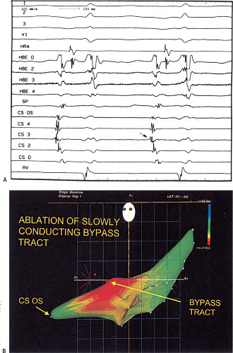 FIGURE 13-38 Ablation of a slowly conducting left posterior bypass tract. In (A), circus movement tachycardia in a slowly conducting bypass tract is present. Note that the earliest activation is seen in CS bipolar pair 3 (arrow). This corresponds to a site 4 cm inside the os of the CS where successful ablation was accomplished guided by electroanatomic mapping (B). |
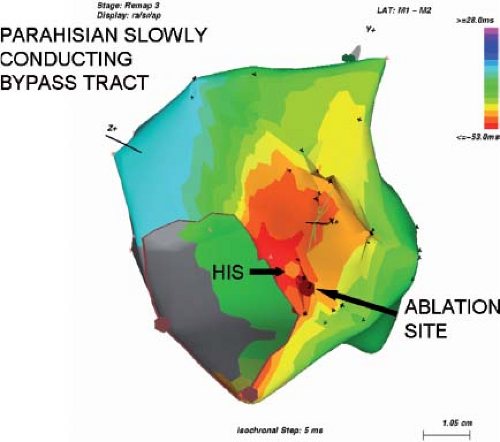 FIGURE 13-39 Ablation of a slowly conducting para-Hisian bypass tract. Atrial activation is color coded in the electroanatomical map during circus movement tachycardia. The His bundle is marked by the orange circle and the ablation sites adjacent to it are shown. The earliest atrial activation is shown in dark red with subsequent activation in lighter red, orange, yellow, green, etc. This bypass tract was successfully ablated without producing heart block. |
Atriofascicular bypass tracts are the other variant of pre-excitation in which ablative techniques have been useful. Although it was originally thought that these pathways were nodofascicular, it is clear that the vast majority of these pathways originate in the anterolateral right atrial tricuspid annulus and act as a secondary conducting system inserting into the distal right bundle branch. While insertion into the myocardium adjacent to the right bundle branch is possible in some cases, the presence of a retrograde V-H interval of less than 25 msec suggests a direct insertion into the right bundle branch itself. These patients suffer from wide complex tachycardias with a left bundle branch block (LBBB) morphology and usually leftward axis, although the axis is variable (see discussion in Chapter 10). While much has been made of the precordial transition point in these tachycardias, it should not be any different from LBBB of any cause, during which ventricular activation proceeds only over the right bundle branch. Direct recordings of this pathway at the anterolateral tricuspid annulus look like a typical A-V junctional recording with an atrial deflection, a sharp spike, and a ventricular deflection. The sharp spike is believed to represent the “Mahaim” fiber, and may indeed represent an equivalent to a His potential in an auxiliary conduction system.131 This bypass tract can be traced along the free wall of the right ventricle to insert into the right bundle branch. Details of the mapping techniques used to prove the presence of an atriofascicular bypass tract were given in Chapter 10. The approach to this bypass tract is via the inferior vena cava and may or may not require a sheath for catheter stability. Most of these bypass tracts can be located along the lateral tricuspid annulus from which the atrial and “Mahaim” potential can be recorded. Catheter positions are shown in Figure 13-40. These bypass tracts are all susceptible to mechanical interruption of conduction and some have used this to guide ablative therapy. When gentle catheter positioning is used, ablation at the lateral tricuspid annulus often gives rise to an accelerated rhythm with a left bundle branch morphology and a retrograde His activation prior to successful ablation (Fig. 13-41). This is analogous to accelerated junctional rhythm observed during A-V nodal modification for A-V nodal reentry (see subsequent section on A-V nodal tachycardia).
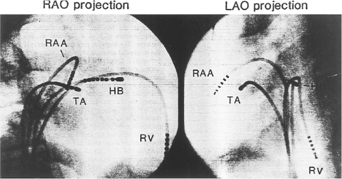 FIGURE 13-40 Catheter position for the ablation of an atriofascicular bypass tract. RAO and LAO projections are shown with the ablation catheter at 10 o’clock on the tricuspid annulus. This is the usual site for the atrial insertion of the atriofascicular bypass tract. See text for discussion. |
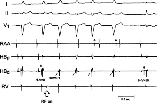 FIGURE 13-41 Catheter ablation of an atriofascicular bypass tract. During sinus rhythm, a retrograde His bundle potential is seen with an H-V interval of 0. During RF application an accelerated rhythm from the atriofascicular bypass tract appears, which is manifested at an accelerated rhythm with the same morphology as the pre-excited rhythm but without an atrial deflection preceding it, yet with a fixed retrograde His preceding it. This then slows and is followed abruptly by loss of pre-excitation and normalization of the QRS with normal AH and H-V intervals. Note the negative T wave in lead V1, which is due to cardiac memory. |
Complications of Procedures
A variety of studies have evaluated procedure-related complications. It is clear that complications are higher in older patients, but are not insignificant in all patients. In the Multicenter European Radiofrequency Survey (MERFS) death occurred in 0.13%, embolic stroke in 0.49% (most of which were reversible), myocardial perforation with pericardial tamponade requiring drainage in nearly 0.8%, complete heart block in 0.6%, arterial or venous thrombosis in 0.36%, and pulmonary embolism in 0.09%.132 A total of 4.4% complication rate was reported. While this seems high I believe it is probably an underestimate since this was a voluntary registry, which is subject to marked bias. With greater experience complication rates go down but still exist. A more recent single center experience demonstrated major complications in 0.8% of SVT ablation procedures.133 In our own laboratory, we have had no deaths or strokes. In the last 22 years we have had only four cases of tamponade, all of which were caused by perforation of the right ventricular pacing catheter, and one arterial-venous fistula. While we routinely use heparin for all ablations, activated clotting times (ACTs) are only followed for left-sided ablations that take longer than 15 minutes in which case they are maintained at 250 to 300 seconds. The majority ablations using the retrograde approach are accomplished after the initial bolus and prior to assessment of the ACT. This is not the case for the transseptal approach, which typically takes longer. Of note, a report by Zhou et al.134 from the Massachusetts General Hospital suggests that heparinization alone may be inadequate to prevent thromboembolism. The development and use of other energy sources, which are less thrombogenic, such as cryoablation, cool-tip RF ablation, and use of direct antithrombin or antiplatelet agents will hopefully decrease this risk. In our laboratory, all patients are routinely heparinized during the acute study, but not following these studies. Patients having right-sided ablation receive a bolus of 2,500 units of heparin and an infusion of 1,000 units per hour. When the left side of the heart is entered for ablation (either transeptally or retrogradely) a 5,000 to 10,000 unit bolus is given, followed by a 1,000 units per hour infusion adjusted to maintain an ACT of 250 to 300 seconds. Following this procedure, heparin is discontinued. In patients who have had left-sided ablations most laboratories anticoagulate patients with warfarin or newer oral anticoagulants for 1 to 3 months. We have used aspirin and have not observed evidence of systemic or pulmonary emboli during or following the procedures. Perhaps this is due to the short procedure time and limited number of lesions delivered. Another feature that may help decrease our embolic rate is the abrupt cessation of delivery of RF energy if there is an impedance rise at all. This is universally associated with coagulum formation at the tip of the standard, nonirrigated catheter with the potential for embolic phenomenon. Another finding associated with coagulum formation is loss of power (<10 W) associated with a rise in temperature, and usually, a minimal change in impedance. These findings suggest poor contact. While we have heretofore escaped any embolic phenomenon with our precautions, the use of cool-tip catheters or cryothermal catheters probably will reduce the incidence of coagulum formation and embolization.
Intraoperative Mapping and Surgical Ablation of Accessory Pathways
With the development of epicardial mapping by Durrer and Roos135 localization of bypass tracts became possible and led to the first successful surgical ablation of the Wolff–Parkinson–White
syndrome by Dr. Will Sealy at Duke University.1,2 This event in fact initiated the concept that arrhythmias could be cured by surgery. While this initially precipitated an explosion of it stimulated the interest of electrophysiologists to develop both surgical and nonsurgical methods to treat a variety of other arrhythmias. With the advent of catheter ablation the surgical approach to the management of Wolff–Parkinson–White syndrome has been relegated to a minor role, only being employed following failure of RF ablation. Since the success rates for RF ablation are greater than 95%, and the remainder of patients are frequently treatable by antiarrhythmic agents, surgical correction of pre-excitation syndromes is a rare event. Nevertheless, in selected patients surgery for failed RF ablation can provide improved quality of life without the need of long-term antiarrhythmic agents. Surgical approaches to Wolff–Parkinson–White syndrome involve the use of both epicardial and endocardial approaches with the adjunctive use of cryosurgery.7,8,9,10 Using these techniques surgical correction of pre-excitation syndromes approaches 100% with an operative mortality of less than 1%. Most cases currently undergoing surgery involve right-sided pathways, multiple pathways, and those associated with congenital abnormalities including Ebstein anomaly, transposition of the great vessels and congenital diverticulae of the coronary venous system. The rarity of the need for surgical intervention is exemplified by the fact that only 15 patients were operated on at Washington University for unsuccessful RF catheter ablation for tachycardias due to accessory pathways in the period between 1990 and 1993.136 Most of the patients were failures because of complex anatomical abnormalities associated with the presence of bypass tracts. One of the important lessons to be learned was that excessive use of RF ablation can obliterate tissue planes in the A-V groove and/or render the tissues in these areas too friable to prohibit safe surgical correction. This further stresses my belief that catheter ablation should be limited to a few sites based on careful mapping and that the use of “insurance” burns as a result of poor mapping techniques should be abandoned. We have had one patient with Ebstein anomaly in whom ablation failed and surgery was undertaken to cure her SVTs and the CONE procedure was performed to repair her tricuspid valve. A 2-cm wide A-V muscular connection was found during intraoperative mapping and the region was treated with extensive cryoablation. One month later intermittent pre-excitation and SVT recurred. Encircling ablation of the atrial breakthrough with a cool-tip catheter was performed and in short-term follow-up she is doing well.
syndrome by Dr. Will Sealy at Duke University.1,2 This event in fact initiated the concept that arrhythmias could be cured by surgery. While this initially precipitated an explosion of it stimulated the interest of electrophysiologists to develop both surgical and nonsurgical methods to treat a variety of other arrhythmias. With the advent of catheter ablation the surgical approach to the management of Wolff–Parkinson–White syndrome has been relegated to a minor role, only being employed following failure of RF ablation. Since the success rates for RF ablation are greater than 95%, and the remainder of patients are frequently treatable by antiarrhythmic agents, surgical correction of pre-excitation syndromes is a rare event. Nevertheless, in selected patients surgery for failed RF ablation can provide improved quality of life without the need of long-term antiarrhythmic agents. Surgical approaches to Wolff–Parkinson–White syndrome involve the use of both epicardial and endocardial approaches with the adjunctive use of cryosurgery.7,8,9,10 Using these techniques surgical correction of pre-excitation syndromes approaches 100% with an operative mortality of less than 1%. Most cases currently undergoing surgery involve right-sided pathways, multiple pathways, and those associated with congenital abnormalities including Ebstein anomaly, transposition of the great vessels and congenital diverticulae of the coronary venous system. The rarity of the need for surgical intervention is exemplified by the fact that only 15 patients were operated on at Washington University for unsuccessful RF catheter ablation for tachycardias due to accessory pathways in the period between 1990 and 1993.136 Most of the patients were failures because of complex anatomical abnormalities associated with the presence of bypass tracts. One of the important lessons to be learned was that excessive use of RF ablation can obliterate tissue planes in the A-V groove and/or render the tissues in these areas too friable to prohibit safe surgical correction. This further stresses my belief that catheter ablation should be limited to a few sites based on careful mapping and that the use of “insurance” burns as a result of poor mapping techniques should be abandoned. We have had one patient with Ebstein anomaly in whom ablation failed and surgery was undertaken to cure her SVTs and the CONE procedure was performed to repair her tricuspid valve. A 2-cm wide A-V muscular connection was found during intraoperative mapping and the region was treated with extensive cryoablation. One month later intermittent pre-excitation and SVT recurred. Encircling ablation of the atrial breakthrough with a cool-tip catheter was performed and in short-term follow-up she is doing well.
Ablation of the A-V Junction for Ventricular Rate Control during Atrial Tachyarrhythmias
Although cure of atrial fibrillation is a goal, and one that will be discussed subsequently, it is not possible in most people and rate control is considered a reasonable option. Unfortunately, pharmacologic rate control is difficult to achieve and/or is associated with side effects leading to poor patient compliance. As such, ablation and/or modification of the A-V junction with subsequent pacemaker implantation is a reasonable alternative in selected patients. The first use of catheter ablation was for the creation of A-V block using high-energy DC shocks.80,81 This technique was the mainstay of creation of A-V block and the primary indication for catheter ablation until the advent and refinement of RF ablative techniques. Since that time RF ablation has replaced high-energy shocks to create A-V block. While data137,138,139 suggested that DC ablation was as effective as RF energy in creating heart block, DC ablation required general anesthesia and was associated with greater morbidity and mortality than RF ablation. DC ablative techniques were associated with subsequent sudden deaths that were related to polymorphic ventricular tachycardia associated with long QT syndromes29,138 typically in patients with severely compromised ventricular function. Several of these patients had polymorphic VT prior to ablation and were placed on type I agents after ablation. The causative role of drugs versus ablation in these patients was not clarified. Sudden death has also been observed after RF A-V node ablation. The cause of this appears to be prolongation in ventricular refractoriness secondary to acute change in ventricular rate, leading to torsade des pointes. As a result most laboratories implant pacemakers programmed to pace at rates of 80 beats/minute or more for a month ablation with gradual reduction in the lower rate afterward.
The major advantage of RF energy is the ability to precisely block the A-V node and leave a junctional escape pacemaker. While this does not obviate the need for permanent pacing it provides reassurance in case of pacemaker failure. Moreover, even if heart block is not created by an attempted A-V nodal ablation one has the alternative of ablating the His bundle directly or accepting a modified A-V node that can conduct, albeit more slowly. Another problem with the DC ablation approach was the lack of control of the delivered energy and associated atrial injury. Most importantly, it was hard to precisely ablate the A-V node so that a junctional escape rhythm would be maintained. Even when A-V nodal block was induced, an RBBB pattern during His bundle escape rhythms was noted suggesting a distal effect of the ablative procedure. Just as frequent was the presence of a fascicular escape rhythm. The reason for the high incidence of His bundle lesions was the requirement for a good His bundle recording on the ablation catheter to assure block of any type appeared. Gallagher et al.82 demonstrated the requirement for specific amplitudes of His bundle recordings to achieve A-V nodal block. Examples of DC catheter ablation–induced intranodal block with a normal and intranodal block with an RBBB are shown in Figures 13-42 and 13-43.
RF ablation has become the dominant mode of achieving A-V block. This technique does not require general anesthesia, and one can more precisely achieve A-V nodal block with it. The method I generally use to achieve A-V nodal block requires secure positioning of a His bundle catheter. The ablation catheter is positioned 2 cm below the third and fourth poles of His bundle catheter (Fig. 13-44). At this site, a very small His deflection may be recorded in approximately half of the cases.
Using temperature control catheters, a target temperature of 65°C is used and with nontemperature control catheters, any energy producing a 10 Ω decrease in impedance is accepted. I believe that regardless of whether temperature or impedance is used as a target, RF energy should begin at 10 W and gradually increased. Sometimes block appears almost immediately and at other times it takes several lesions to produce block. Typically, when one is at a good site to ablate, a junctional rhythm is induced with delivery of RF energy. Occasionally, following the development of complete heart block transient resumption of A-V conduction can be observed, which is subsequently followed by late heart block. The recognition of a potential for late development of A-V block after early resumption of a conduction following ablation-induced transient A-V block, mandates use of a pacemaker in whom transient A-V block is produced. We arbitrarily use 3 to 5 minutes of complete A-V block as a time frame for consideration of a permanent pacemaker. Patients with otherwise normal hearts have a 95% success rate. Patients who are most difficult to ablate are those with longstanding heart failure, hypertension, or other disorders in which atrial enlargement or hypertrophy is noted. On occasion, one has to ablate the His bundle either on the right side, or even on rare occasion on the left side to achieve A-V block. Our success rate in achieving A-V nodal block in such cases is approximately 85%. The vast majority of these patients maintain an escape rhythm in follow-up. An example of a patient with a cardiomyopathy and uncontrolled atrial fibrillation who underwent A-V nodal ablation is shown in Figure 13-45. In the 1998 NASPE Registry116 the acute success rate for achieving complete heart block was 97.6% with only a 3% risk of recurrence of A-V conduction. Randomized comparisons of ablation versus medical therapy for rate control demonstrate better rate control improvement in left ventricular function, and improved quality of life with ablation.140,141,142
Using temperature control catheters, a target temperature of 65°C is used and with nontemperature control catheters, any energy producing a 10 Ω decrease in impedance is accepted. I believe that regardless of whether temperature or impedance is used as a target, RF energy should begin at 10 W and gradually increased. Sometimes block appears almost immediately and at other times it takes several lesions to produce block. Typically, when one is at a good site to ablate, a junctional rhythm is induced with delivery of RF energy. Occasionally, following the development of complete heart block transient resumption of A-V conduction can be observed, which is subsequently followed by late heart block. The recognition of a potential for late development of A-V block after early resumption of a conduction following ablation-induced transient A-V block, mandates use of a pacemaker in whom transient A-V block is produced. We arbitrarily use 3 to 5 minutes of complete A-V block as a time frame for consideration of a permanent pacemaker. Patients with otherwise normal hearts have a 95% success rate. Patients who are most difficult to ablate are those with longstanding heart failure, hypertension, or other disorders in which atrial enlargement or hypertrophy is noted. On occasion, one has to ablate the His bundle either on the right side, or even on rare occasion on the left side to achieve A-V block. Our success rate in achieving A-V nodal block in such cases is approximately 85%. The vast majority of these patients maintain an escape rhythm in follow-up. An example of a patient with a cardiomyopathy and uncontrolled atrial fibrillation who underwent A-V nodal ablation is shown in Figure 13-45. In the 1998 NASPE Registry116 the acute success rate for achieving complete heart block was 97.6% with only a 3% risk of recurrence of A-V conduction. Randomized comparisons of ablation versus medical therapy for rate control demonstrate better rate control improvement in left ventricular function, and improved quality of life with ablation.140,141,142
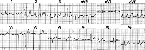 FIGURE 13-42 Twelve-lead ECG following optimal DC His ablation. A narrow QRS complex with complete A-V block is shown. Note the reasonable escape rate. |
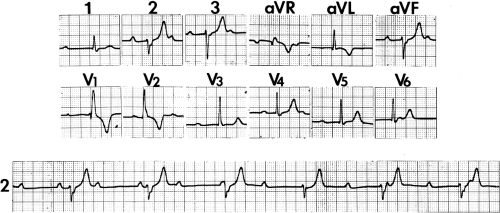 FIGURE 13-43 Escape rhythm with RBBB following DC ablation of the A-V junction. If ablation is performed too distally, right bundle branch block frequently develops. This is most likely a fascicular rhythm because of the relatively “narrow” QRS. Note the presence of left axis deviation. See text for discussion. |
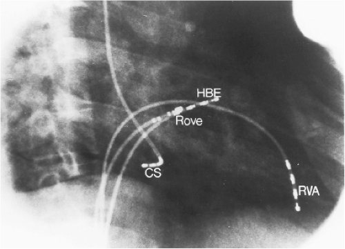 FIGURE 13-44 Appropriate catheter position for the production of A-V nodal block. In the RAO projection, the ablation catheter is moved just subjacent to the proximal poles of the His bundle catheter. A small His deflection may or may not be seen in this position at which site block when produced is almost always in the A-V node with a good junctional escape rhythm. |
Because the requirement for a pacemaker, several groups attempted to develop a strategy of A-V nodal modification to reduce the rate response during atrial fibrillation without producing heart block.100,143 This procedure is a hit and miss attempt to injure the A-V node without producing A-V block. There are several limitations to this approach. First, it is only applicable to patients who do not have symptoms due to an irregular heart rhythm. Second, at least 25% of the patients in whom it is attempted develop inadvertent complete A-V block. Third, its long-term success is uncertain.144 Fourth, an irregular rhythm may be hemodynamically less efficient than a regular rhythm. As such, it is our approach to attempt to achieve complete A-V nodal block. Implantation of a pacemaker in fact is well received by most of our patients.
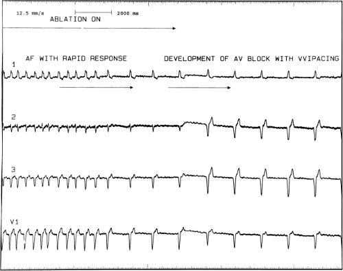 FIGURE 13-45 Demonstration of radiofrequency-induced A-V block to control ventricular response and atrial fibrillation. Atrial fibrillation with a rapid response is present in the patient with cardiomyopathy despite beta blockers and digoxin. Radiofrequency ablation with the catheter positioned as shown in Figure 13-44 produced A-V nodal block almost immediately with a good junctional escape. VVI pacing at a rate of 60 (junctional rate 50) takes over on the right-hand side of the tracing. |
Several studies have been performed with the hypothesis that biventricular pacing would be superior to RV pacing following A-V junction ablation.145,146 Although the level of evidence is not extraordinary, biventricular pacing is commonly used in this setting, particularly in the setting of pre-existing structural heart disease. Conversely, in patients with atrial fibrillation in whom cardiac resynchronization therapy is used for the treatment of heart failure, many advocate A-V junction ablation, particularly in nonresponders, to reduce the percentage of conducted (and therefore nonbiventricularly paced) beats.147
Catheter Ablation Techniques to Treat A-V Nodal Tachycardia
A-V nodal reentrant tachycardia is the most common form of supraventricular tachycardia, being responsible for more than half of the cases. The exact pathophysiologic substrate for A-V nodal reentrant tachycardia is still uncertain and remains under appropriate active investigation. My own personal research of the interpretation of the data concerning the pathophysiology of A-V nodal reentry is detailed in Chapter 8. Basically a few points should be made that are generally agreed upon. First, there are no anatomic specific pathways that have
been described that correlate with the fast and slow A-V nodal pathways. Second, slow pathway potentials as described by Jackman et al.148 and Haissaguerre et al.149 are nonspecific electrograms that may be found in all individuals and represent composite electrograms of superficial and deep atrial and/or nodal tissues that can be found in the midtriangle of Koch.150 This is schematically shown in Figure 13-46. Third, although A-V nodal reentry with short retrograde conduction times (typical A-V nodal reentry) usually has the earliest retrograde atrial activation recorded near the apex of the triangle of Koch and the uncommon variety of A-V nodal reentry (so called fast-slow A-V nodal reentry) usually has its earliest atrial activation recorded at the base of the triangle of Koch or in the os of the coronary sinus, many exceptions occur. More importantly, detailed mapping of the entire triangle of Koch and the coronary sinus shows multiple breakthroughs of activation during A-V nodal reentrant tachycardia (see Chapter 8). Fourth, I believe use of slow–slow, fast–slow, and slow–fast A-V nodal reentry (with the terms “fast” and “slow” defined by apical or basal breakthroughs of activation) to be confusing. As such, the concept of identifying early sites of activation during A-V nodal reentry or ventricular pacing and using them to guide ablation does not make sense. I believe that we as electrophysiologists have been ablating this arrhythmia without precise knowledge of the pathophysiologic substrate for the arrhythmia and have been lucky with the good outcomes that have resulted from ablation. For example, in our laboratory the pattern of retrograde atrial activation has not at all influenced our ablation methods, and our success rates, which exceed 97%, are no different than those of other laboratories in which alleged directed attention to specific electrograms has been used. In my opinion this only serves as testimony as to how ignorant we are about the true nature of A-V nodal tachycardia. That being said, current catheter-based techniques to modify the A-V node and cure A-V nodal reentry are highly successful.
been described that correlate with the fast and slow A-V nodal pathways. Second, slow pathway potentials as described by Jackman et al.148 and Haissaguerre et al.149 are nonspecific electrograms that may be found in all individuals and represent composite electrograms of superficial and deep atrial and/or nodal tissues that can be found in the midtriangle of Koch.150 This is schematically shown in Figure 13-46. Third, although A-V nodal reentry with short retrograde conduction times (typical A-V nodal reentry) usually has the earliest retrograde atrial activation recorded near the apex of the triangle of Koch and the uncommon variety of A-V nodal reentry (so called fast-slow A-V nodal reentry) usually has its earliest atrial activation recorded at the base of the triangle of Koch or in the os of the coronary sinus, many exceptions occur. More importantly, detailed mapping of the entire triangle of Koch and the coronary sinus shows multiple breakthroughs of activation during A-V nodal reentrant tachycardia (see Chapter 8). Fourth, I believe use of slow–slow, fast–slow, and slow–fast A-V nodal reentry (with the terms “fast” and “slow” defined by apical or basal breakthroughs of activation) to be confusing. As such, the concept of identifying early sites of activation during A-V nodal reentry or ventricular pacing and using them to guide ablation does not make sense. I believe that we as electrophysiologists have been ablating this arrhythmia without precise knowledge of the pathophysiologic substrate for the arrhythmia and have been lucky with the good outcomes that have resulted from ablation. For example, in our laboratory the pattern of retrograde atrial activation has not at all influenced our ablation methods, and our success rates, which exceed 97%, are no different than those of other laboratories in which alleged directed attention to specific electrograms has been used. In my opinion this only serves as testimony as to how ignorant we are about the true nature of A-V nodal tachycardia. That being said, current catheter-based techniques to modify the A-V node and cure A-V nodal reentry are highly successful.
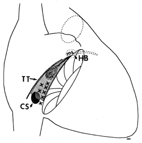 FIGURE 13-46 Location of “slow pathway” potentials. A schema of the triangle of Koch is shown. Hatched areas are those over which multicomponent potentials that are believed by some to represent slow pathway potentials are seen. TT, tendon of Todaro; CS, coronary sinus; MS, membranous system. |
Initially high-energy DC shocks were used to modify the A-V node. This form of energy has totally been replaced by the use of RF energy sources.96,97,98,99,100,148,149,150,151,152,153,154 Ablation at the apex of the triangle of Koch in the region where earliest atrial activation over the “fast” pathway was highly successful (greater than 90%) but was associated with an unacceptably high incidence of development of A-V block of nearly 10%. Even with successful ablation there was lengthening of the PR interval and retrograde conduction block (Fig. 13-47). This led many investigators to conclude that ablation in this region selectively destroys the fast pathway. However, if only fast pathway conduction is effected by ablation, one must explain the absence of retrograde conduction over the slow pathway. The fact that antegrade fast pathway conduction is present but slower, and the absence of V-A conduction, suggests the possibility that the area in which the fast and slow pathway are joined distally and that part of the lower final common pathway were involved in the ablation injury. This could account for the failure of retrograde fast pathway conduction in the presence of even slower antegrade slow pathway conduction (i.e., the absence of A-V nodal tachycardia episodes). Although approximately 50% of the patients with successful ablation at this site demonstrate the absence of dual pathways, in occasional cases, dual A-V nodal pathways are still present, and in some V-A conduction remains intact, and even unimpaired. An example of “retrograde fast pathway” ablation is shown in Figure 13-48. In an attempt to decrease the incidence of A-V block some investigators suggested using lower energies with the immediate cessation on appearance of PR prolongation. Another marker for impending heart block was the development of very rapid accelerated junctional rhythms associated with loss of retrograde conduction. Both of these phenomena are a good sign of impending A-V block should application of energy continue.
In an attempt to decrease the likelihood of A-V block during A-V nodal modification Roman et al.154 suggested ablation of the “slow pathway,” which he and his colleagues believe is adjacent to the coronary sinus near the tricuspid valve. RF energy delivered at this site can prevent A-V nodal reentry without producing antegrade heart block or producing impairment of block of retrograde conduction. They interpreted these results to mean that successful ablation is achieved by selectively blocking the so-called slow pathway. An example of the recording from the presumed antegrade “slow pathway” is shown in Figure 13-49. As noted above, retrograde conduction is usually unimpaired, even if the antegrade slow pathway is ablated (Fig. 13-50). In approximately 40% of cases, dual pathways are still present postablation, but sustained A-V nodal reentry cannot be induced. Single A-V nodal echo complexes are observed in three-fourths of the patients with dual pathways, with block always occurring antegradely in the “slow pathway.” Successful ablation is typically associated with an accelerated junctional rhythm with intact 1:1 retrograde conduction (Fig. 13-51). PR prolongation is
generally not noted. However, on occasion we have seen patients in whom ablation in the inferior part of the triangle of Koch has produced loss of retrograde (V-A) conduction, and we have also demonstrated the absence of retrograde conduction over the fast pathway with the maintenance of dual A-V nodal pathways antegradely. We have occasionally noted development of transient complete heart block with ablation at the inferior portion of the triangle of Koch, at the level of the os of the coronary sinus. One such patient developed block in the lower final common pathway with persistence of A-V nodal tachycardia during the first delivery of RF energy. Retrograde fast pathway block followed the second application of RF energy (Fig. 13-52). Of note, despite retrograde block in the “fast” pathway, antegrade conduction over the “fast” pathway remains unaffected in the sinus beat following termination of SVT. This further supports the functional nature of conduction through the A-V node, and certainly demonstrates that antegrade and retrograde conduction over the “fast” pathway are not necessarily the same. In general, higher RF energies can be delivered in the region of the so-called “slow” pathway without fear of producing A-V block. Unfortunately, exceptions are not rare. We have encountered the least transient block of the retrograde fast pathway in ∼20% of cases in which RF energy was delivered between the os of the coronary sinus at its superior aspect and the tricuspid valve. The reason for this is uncertain, but likely results from proximity to the posterior extension of the A-V node at the superior aspect of the CS os (which is often large in patients with AVNRT).
generally not noted. However, on occasion we have seen patients in whom ablation in the inferior part of the triangle of Koch has produced loss of retrograde (V-A) conduction, and we have also demonstrated the absence of retrograde conduction over the fast pathway with the maintenance of dual A-V nodal pathways antegradely. We have occasionally noted development of transient complete heart block with ablation at the inferior portion of the triangle of Koch, at the level of the os of the coronary sinus. One such patient developed block in the lower final common pathway with persistence of A-V nodal tachycardia during the first delivery of RF energy. Retrograde fast pathway block followed the second application of RF energy (Fig. 13-52). Of note, despite retrograde block in the “fast” pathway, antegrade conduction over the “fast” pathway remains unaffected in the sinus beat following termination of SVT. This further supports the functional nature of conduction through the A-V node, and certainly demonstrates that antegrade and retrograde conduction over the “fast” pathway are not necessarily the same. In general, higher RF energies can be delivered in the region of the so-called “slow” pathway without fear of producing A-V block. Unfortunately, exceptions are not rare. We have encountered the least transient block of the retrograde fast pathway in ∼20% of cases in which RF energy was delivered between the os of the coronary sinus at its superior aspect and the tricuspid valve. The reason for this is uncertain, but likely results from proximity to the posterior extension of the A-V node at the superior aspect of the CS os (which is often large in patients with AVNRT).
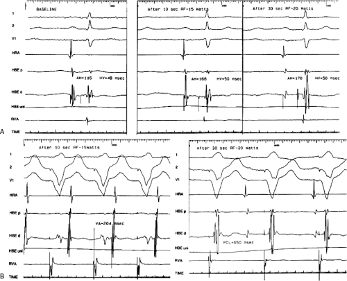 FIGURE 13-47 Modification of “fast pathway” with radiofrequency energy to “cure” typical A-V nodal reentry. A: Three panels are shown during sinus rhythm in a patient with typical A-V nodal reentry. Left: The control AH is 116 msec. Following 10 seconds of RF energy using 15 W, the AH increases to 168 msec without significant change in H-V. Following 30 seconds of 20 W, the AH remains at 170 msec. B: V-A conduction is shown during pacing at 650 msec in the control state and following delivery of RF energy. Good V-A conduction was present in control (not shown). V-A conduction prolongs to 204 msec following 10 seconds of 15 W (top), and V-A block is produced following 30 seconds at 20 W (bottom). PCL, paced cycle length. |
As described in Chapter 8, detailed mapping of the triangle of Koch and coronary sinus has revealed heterogeneous atrial activation during A-V nodal reentry (Fig. 13-53).155 These data are consistent with experimental studies using hundreds of simultaneous recording sites156 and intraoperative mapping in humans157 which fails to demonstrate reentrant excitation. A
number of patients were noted to have nearly simultaneous activation of the apex and base of the triangle of Koch (the so-called slow pathway region) as well as additional breakthroughs in the coronary sinus. Patients in whom such activation patterns are noted appear to be at higher risk for the development of transient and/or permanent A-V block. As such, we always carefully map the apex and base of the triangle of Koch and coronary sinus. If atrial activation at the apex and base of the triangle of Koch occur within 5 msec of one another, we use temperatures initially set at 55°C beginning at the inferior border of the coronary sinus os at the tricuspid annulus. During the accelerated junctional rhythm at such sites atrial pacing is often performed to assure maintenance of 1:1 antegrade conduction. The optimal response to RF ablation should be: (a) loss of conduction over the slow pathway, (b) an increase in Wenckebach cycle length, (c) an increase in the effective refractory and functional refractory period of the A-V node, (d) no effect or shortening of the A-H interval in sinus rhythm, and (e) preservation without change in retrograde conduction. The mechanism of producing junctional rhythms is unclear. While some believe this is due to thermal injury of the “slow” pathway, studies in our laboratory158 suggest that this may be produced by either uncoupling of the superficial atrium from the underlying transitional cells or A-V node, and/or nonspecific heating of the subatrial transitional nodal cells, which in both instances can result in automatic firing. Change in detailed retrograde activation during junctional rhythms when compared to A-V nodal reentry is more consistent with the latter hypothesis. An example of subtle but definite qualitative and quantitative changes in retrograde conduction during
junctional rhythm as compared to atrial activation during A-V nodal tachycardia is seen in Figure 13-54. A schema of these two hypotheses is shown in Figure 13-55.
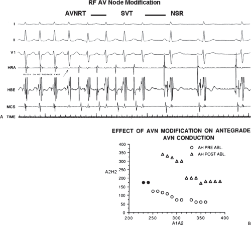 FIGURE 13-48 A: Retrograde fast-pathway ablation by radiofrequency energy during A-V nodal reentry. A-V nodal reentrant tachycardia (AVNRT) is present for the first four complexes. Radiofrequency energy is delivered, resulting in block of conduction in the retrograde fast pathway (arrow). Sinus rhythm resumes following four complexes of an atrial tachycardia. B: Effect of successful radiofrequency ablation of “fast pathway” on A-V nodal response to atrial extrastimuli. The response of AH (vertical axis) to atrial extrastimuli (horizontal axis) pre-RF and post-RF ABL is shown. Before ABL, typical dual A-V pathways and reentry are shown. Following RF ABL of the retrograde “fast” pathway, dual A-V nodal pathways persist. Conduction time and refractoriness of both fast and slow pathways are increased, and no A-V nodal reentry was observed. See text for discussion. |
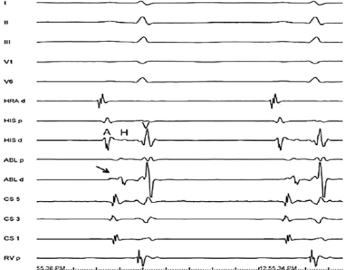 FIGURE 13-49 Recording from site targeted for “slow pathway” ablation. Five surface leads are shown with HBE and CS recordings. The ablation catheter is positioned at a site targeted for slow pathway ablation. Note the ablation site (ABLd) demonstrates a low-amplitude slow component followed by a high-frequency component, both of which occur significantly later than atrial activity in the HBE. |
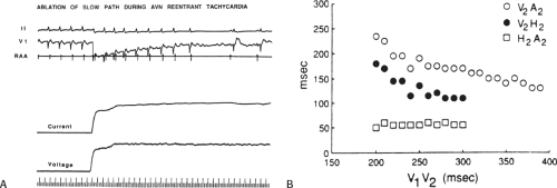 FIGURE 13-50 A: Anterograde “slow-pathway” ablation during SVT. ECG lead II and Vl and electrograms from the RAA are shown. During typical AVNRT SVT, RF energy slows, then terminates SVT by block in the slow pathway. B: Retrograde conduction following ablation of the “slow pathway.” Retrograde conduction in response to VPCs is slow. Conduction times are plotted on the vertical axis, and coupling intervals of VPCs are on the horizontal axis. Note the constant H-A interval with parallel VH and V-A curves—a normal response. |
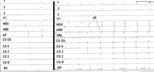 FIGURE 13-51 Junctional rhythm associated with successful RF application. The site of ablation is shown in sinus rhythm on the left. Note the “late” local atrial electrogram at the SP. RF energy applied at this site produces an accelerated junctional rhythm (right). |
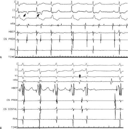 FIGURE 13-52 Radiofrequency ablation of fast pathway from the region of the coronary sinus. A: During A-V nodal reentry RF ablation to area between the CS and tricuspid valve produces block in lower final common pathway; inverted P waves continue for first 2 beats (arrows). This is followed by sinus rhythm and A-V block. B: After resumption of conduction, A-V nodal reentry was induced. Repeat RF ablation at 10 W produces block in retrograde fast pathway followed by sinus rhythm (arrow marks sinus capture). See text for discussion. |
Two methods have been suggested to guide ablation of the slow pathway. Roman et al.154 and Jackman et al.148 suggest that certain characteristics of the electrogram recorded between the coronary sinus and tricuspid valve represent slow pathway potentials. These characteristics include electrograms with multicomponents of varying amplitudes and frequency that occur after the local coronary sinus electrogram and the atrial electrogram in the His bundle recording site. The initial potential is usually a low-frequency hump followed by a higher-frequency component that may occur as late as the His bundle. This so-called slow pathway electrogram is associated with a large ventricular complex (A-V ratio of less than 0.3). In my experience, as well as that of others,148,150 similar multicomponent low- and high-amplitude potentials are observed in the vast majority of normal patients without any arrhythmias or dual A-V nodal physiology. In addition, these potentials may be found over a large area in the lower half of the triangle of Koch (Fig. 13-56). Whether these potentials represent nodal tissue (transitional cells with dead-end pathways), anisotropic conduction through atrial fibers around the coronary sinus or combinations of both is unclear. Additional types of slow pathway potentials have been described by Haissaguerre et al.149 These electrograms are low-amplitude potentials, which exhibit decremental conduction and are believed to represent nodal cells. As with the potentials described by Jackman et al.123 these potentials are also found in
patients without A-V nodal tachycardia or dual pathway physiology. In both instances experimental work has demonstrated that these types of “slow pathway potentials” are actually composite electrograms reflecting electrical activity both near and distant, from different tissues. As such they do not represent any specific pathophysiologic substrate but merely an anatomic site in which these tissues overlie one another. The second method that has been more widely employed is an anatomic approach in which there is a stepwise positioning of the ablation catheter from low in the triangle of Koch to more superior areas.151 The catheter is first placed at the base of the triangle of Koch at the level of the inferior portion of the os of the coronary sinus with the tip at the tricuspid annulus to record a large ventricular electrogram and a small atrial electrogram. RF energy is delivered, and if no junctional rhythm is produced the catheter is moved superiorly by a few millimeters. Repeated delivery of RF energy is applied until an accelerated junctional rhythm is noted. RF energy is maintained for approximately 1 minute, after which stimulation is performed to assess the effect of ablation. The most successful sites of ablation are just at the anterior aspect of the os of the coronary sinus at the tricuspid valve. According to these investigators, approximately one-third of patients require ablation superior to the os. Although ablation above the level of the “ceiling” of the coronary sinus can be effective for ablation of A-V nodal tachycardia, these would be considered midseptal sites, and the risk of heart block is much higher. Care must be taken to assure that the distal ablation pair is recording a very large ventricular electrogram with only a small atrial electrogram. Delivery of energy to a more posterior position in which the atrial and ventricular electrograms are equal in amplitude may result in A-V block. In our laboratory we use a combination of approaches. We generally start with an ablation lesion delivered at the level of the CS of the coronary sinus adjacent to the tricuspid valve where a multicomponent delayed atrial electrogram is observed. RF energy is delivered with a temperature of 60° to 65°C. The atrial EGM is often activated 30 to 40 msec later than the atrial electrogram recorded on the HBE. The
development of a rapid junctional rhythm or loss of retrograde conduction, or increase in the PR interval of conducted beats mandates immediate cessation of RF delivery. Using this technique we have had success in 320 out of 325 consecutive cases, and only one incidence of complete A-V block. Block occurred almost instantly when energy was delivered at the level of the CS at the tricuspid valve. Such events are humbling and make one realize how little we know about the A-V junction.
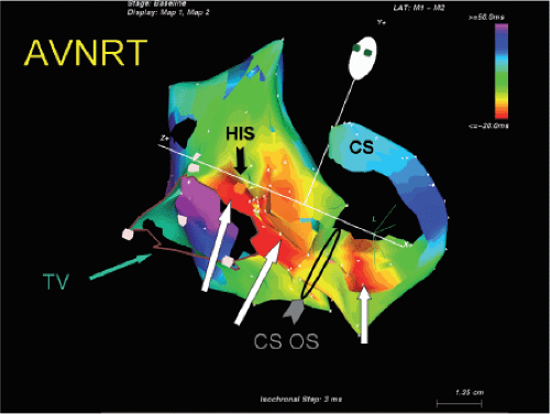 FIGURE 13-53 Heterogeneous activation of the triangle of Koch and coronary sinus in AVNRT. Electroanatomic mapping of AVNRT is shown in a tilted LAO (top) view. Some of the wall has been removed to allow visualization of the triangle of Koch. This is an isochronal map with 3 msec isochrones from red (earliest) to purple (latest). The entire triangle of Koch is activated nearly simultaneously (white arrows). An additional early breakthrough is seen in the CS (white arrow). The His, CS os and tricuspid valve (TV) are marked. No evidence of reentrant excitation is seen. |
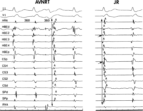 FIGURE 13-54 Subtle differences in atrial activation during AVNRT and junctional rhythm. AVNRT on the left and junctional rhythm on the right demonstrate subtly different qualitative and quantitative atrial activation patterns (see text and Chapter 8). |
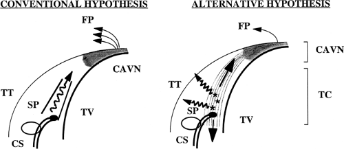 FIGURE 13-55 Proposed mechanism for junctional rhythm during RF ablation. The conventional hypothesis (left) suggests that the slow pathway is stimulated, producing the identical activation pattern as AVNRT. Our hypothesis is that the tissue ablated is both stimulated and uncoupled (atrium from the transitional cells, and possibly the posterior extension of the compact A-V node) to produce a variable pattern of atrial activation. See Chapter 8 for detailed discussion. |
In occasional patients earliest retrograde atrial activation is in the CS with later activation in the slow pathway region or the apex of the triangle of Koch. We have seen 18 such examples in 222 consecutive patients.159 In all of our cases successful ablation has been accomplished with the standard approach described above. Others, however, have noted occasional incidences in which ablation in the coronary sinus or even the left side of the heart may be necessary.126,160,161,162 The mechanism by which ablation works in these cases is unclear. Anatomically one must remember the A-V node is a subepicardial cardiac structure lying between the two atria just anterior to the CS OS. It is not surprising therefore that ablation in the CS os can injure the A-V node itself and terminate A-V nodal tachycardia. Earlier experience in the surgery of posteroseptal bypass tracts clearly demonstrated that cryothermal lesions underneath the coronary sinus toward the apex of the triangle of Koch could produce heart block. A-V nodal reentry requiring ablation in the lateral CS or left atrium has been reported, but is quite rare.126,163
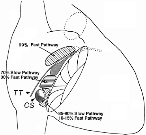 FIGURE 13-56 Relation of site of ablation to block in “fast” or “slow” pathway. The triangle of Koch is schematically shown as in Figure 13-46. Three regions are shown with the results of RF ablation at these sites. There is overlap in site of RF application and resultant A-V nodal conduction. See text for discussion. |
How ablation works to “cure” A-V nodal reentry is not clear. While a few postmortem studies of patients in whom A-V nodal ablations had been performed have demonstrated intact compact nodes, the amount of injury to the transitional cells, injury but not death to the compact node, and effect of uncoupling of superficial atrial fibers from the subjacent compact nodal transitional cells is not understood. The lack of an absolute relationship for RF-induced block of the “fast” or “slow” pathways to the site of RF application supports this notion. The relationship of ablation of “fast” and “slow” pathway to the site of delivery of RF in our first 300 cases of ablation for A-V nodal reentrant SVT is shown in Figure 13-56. We have seen three “slow” pathway blocks produced by lesions delivered at the apex of the triangle of Koch. Both had prior ablations at other institutions. No discrete anatomic pathways have ever been described. Nonspecific effects altering summation and inhibition of A-V nodal conduction as well as the anisotropy of the compact node and transitional cells are probable contributing factors to the successful ablation of A-V
nodal tachycardia. The persistence of dual A-V nodal pathways in 40% of patients who remain free of clinical arrhythmias suggests an alteration in the functional capabilities of the circuit to perpetuate themselves, perhaps related to change in the size of the potential reentrant circuit (e.g., smaller) such that a greater (steeper) curvature is needed to turn around in the smaller space, which results in the failure of conduction.
nodal tachycardia. The persistence of dual A-V nodal pathways in 40% of patients who remain free of clinical arrhythmias suggests an alteration in the functional capabilities of the circuit to perpetuate themselves, perhaps related to change in the size of the potential reentrant circuit (e.g., smaller) such that a greater (steeper) curvature is needed to turn around in the smaller space, which results in the failure of conduction.
I do not think the results of ablation provide any clue in helping to resolve the issue of whether or not some part of the atrium is required for A-V nodal reentry. Clearly, in the vast majority of, if not in all, cases, successful ablation is associated with a change in A-V nodal conduction of one form or another. In addition, successful ablation almost always is associated with the induction of junctional rhythms and not ectopic atrial rhythms. Most A-V nodal conduction curves following A-V nodal modification demonstrate an upward shift to the right of one or both pathways following successful ablation. Regardless of the site of ablation, dual A-V nodal pathways may still be present, conduction over the fast or slow pathway may be slower, yet no A-V nodal tachycardia results.
The overall success rate of modification of the A-V node to cure A-V nodal reentrant tachycardia can be expected to exceed 95%.116,117 The success rates are similar whether ablation is aimed at the retrograde fast pathway or antegrade slow pathway, or whether this is anatomically guided (i.e., ablating superior or inferior in Koch triangle) or electrogram-guided. Whether energy is delivered during SVT or sinus rhythm does not appear to influence the results, although it is easier to maintain a stable catheter position in sinus rhythm. The major reason why ablation should be carried out in sinus rhythm and not during SVT is that an unstable catheter position may result in inadvertent A-V block. In summary, the delivery of RF energy to the posterior third of the triangle of Koch has a high efficacy rate of curing A-V nodal tachycardia. The exact mechanism by which this works is uncertain. While accelerated junctional rhythms appear to be necessary to achieve successful ablation, they are not necessarily sufficient. The ideal end points include loss of slow pathway conduction, a prolonged Wenckebach cycle, and persistence of intact antegrade and retrograde conduction. Persistence of dual pathways is seen in 40%. If dual pathways are present with single echo complexes, recurrent clinical A-V nodal reentry is rare. We accept an echo zone associated with dual pathways of 30 msec or less. If dual pathways or single echoes can be produced over a wide range of coupling intervals, we have found that the addition of isoproterenol and/or atropine often induces more sustained A-V nodal tachycardia. As such we usually give additional lesions until an echo zone of 30 msec or less or loss of slow pathway conduction is achieved. In all instances, prior to termination of the study, stimulation is repeated following isoproterenol and/or atropine. Absence of slow pathway conduction or a very narrow window of slow pathway conduction is associated with a recurrence rate of less than 2%.
The major complication of RF ablation to cure A-V nodal tachycardia is the development of heart block. The risk of heart block appears to be less than 1% and does not seem to be able to be improved upon no matter how careful the investigator. Congenital abnormalities are often associated with displacement of the A-V node, and a forme fruste of these congenital abnormalities (which may go undetected) may be related to inadvertent A-V block. In the absence of complete heart block, prolonged A-V conduction can be produced, which can lead to a pacemaker syndrome or exercise intolerance, should Wenckebach occur at fast rates. Fortunately these complications are extremely rare. Controversy exists as to how to deal with patients who have failed ablations. While some believe that prior slow pathway ablation indicates a high incidence of A-V block should fast pathway ablation be undertaken and vice versa, the data supporting this fear is at best limited. While in most instances repeated ablation in the similar region of a prior failed ablation is sufficient, occasionally one must deliver RF energy at the opposite region—either near the os of the CS or in the fast pathway region. We have not had any evidence of A-V block in the nearly dozen patients who have been referred to us for failed ablations elsewhere. It is, however, a generally held belief that repeated ablations for A-V nodal tachycardia are associated with a higher risk of A-V block, and patients should be made aware of this.
Cryoablation is used in some centers, particularly in pediatric electrophysiology, in an attempt to reduce the risk of inadvertent A-V block. Although the use of larger tip (6 mm) catheters has eliminated the concept of cryomapping, cryoablation certainly offers the security of perfect catheter stability during energy delivery. Recent comparative studies of cryoablation and RF have been rather uniform in the following conclusions: (1) the incidence of heart block with RF is quite low, but essentially not seen with cryoablation; (2) acute procedural success is high (96% to 100%) with both methods and recurrence is higher with cryoablation (9% to 15%).63,164
Junctional Tachycardia
Junctional tachycardia, which has a focal, nonreentrant mechanism, is important to distinguish from A-V nodal tachycardia. Although traditionally it is associated with digitalis toxicity or in the early period following cardiac surgery, it also has a paroxysmal form and may cause significant symptoms. Various maneuvers have been proposed to distinguish these two arrhythmias. If an atrial extrastimulus is delivered during tachycardia when the His is refractory perturbs the timing of the next His, this confirms participation of the slow pathway, consistent with A-V nodal tachycardia. Alternatively, if an earlier extrastimulus advances the timing of the His immediately following without terminating the tachycardia, this indicates that the retrograde fast pathway is not required for the maintenance of the tachycardia, diagnosing junctional tachycardia.165 Overdrive pacing during tachycardia has also been used for this purpose, observing the response upon cessation: atrial-His-His-atrial response in junctional tachycardia and an atrial-His-atrial response in A-V nodal tachycardia.166 These maneuvers may also be helpful immediately following slow pathway ablation, to distinguish between recurrent
AVNRT and the frequent occurrence of nonsustained junctional rhythm following atrial stimulation, particularly during isoproterenol administration.
AVNRT and the frequent occurrence of nonsustained junctional rhythm following atrial stimulation, particularly during isoproterenol administration.
Ablation of junctional tachycardia can be successful, but is not as effective as for A-V nodal tachycardia and has a higher incidence of heart block. Most reports of ablation in this circumstance are in pediatric patients. The largest included 11 patients (including 5 adults), and ablation was successful without heart block in 9 patients. The strategy in this series was ablation at the site of earliest atrial activation in patients with V-A conduction, and empiric slow pathway ablation in the setting of V-A block.167 Cryoablation has also been used in this application with reasonable success.168
Surgical and Catheter Ablation Techniques to Manage other Atrial Arrhythmias
Atrial arrhythmias that have been ablated either surgically or through the delivery of energy have included atrial tachycardias, atrial flutter, and atrial fibrillation.10,11,12,13 Catheter ablation has clearly become the treatment of choice for atrial tachycardia and atrial flutter, for which excellent results can be expected. Ablation for atrial fibrillation is widely performed using catheter and surgical techniques; the optimal indications for either strategy are still being determined.
Ablation of Atrial Tachycardia
Atrial tachycardias that are incessant and due to abnormal automaticity or triggered activity are often drug refractory and as such are most often treated by ablation. Microreentrant atrial tachyarrhythmias are more easily managed with drugs so that ablation is not usually considered until there is a drug failure. Macroreentrant atrial tachycardias are more like atrial flutter and will be discussed in that subsection.
Incessant atrial tachycardias are an important cause of tachycardia-mediated cardiomyopathy. They are also difficult to treat with antiarrhythmic agents. These atrial tachycardias can occur from a wide variety of areas in the heart but seem to have the propensity for the crista terminalis, both atrial appendages, the coronary sinus, the regions of the mitral and tricuspid annulae, as well as the pulmonary veins. Why these structures are prone to develop these rhythms is unclear.169,170,171,172,173,174,175
Since the vast majority of incessant atrial tachycardias are focal in origin and due to abnormal automaticity or triggered activity, the goal of mapping is to find the earliest site of activation. It is important to recognize that sedation of these patients might terminate the tachycardia. If the tachycardias are not incessant, catecholamine infusion and/or use of theophylline or atropine (in the case of a catecholamine-mediated triggered activity) may be necessary to induce the arrhythmia. The first step in mapping atrial tachycardias is using the electrocardiogram to regionalize the source of the arrhythmia. P waves associated with tachycardias arising in the crista have a right-to-left orientation such that they are positive and broad in leads I and II and positive in the aVL. They are also biphasic in lead V1. Tachycardias arising in the septum near the os of the CS have inverted P waves in the inferior leads with positive P waves in aVR and aVL. P waves in tachycardias arising in the left atrial appendage are positive in II, III, and aVF with III being more positive than lead II and positive in V1. These are not too dissimilar from the left superior pulmonary vein P waves, which are positive in II, III, and aVF and upright in V1. Those tachycardias arising from the right superior pulmonary veins are narrower with positive orientation in II, III, and aVF with II and III being similar and biphasic to slightly positive in lead V1. They are isoelectric in lead I. In general, P waves associated with tachycardias arising near the septum are narrower than those arising on the right or left free wall. Once seen, the P wave is analyzed and the tachycardia origin regionalized. A systematic approach can then be planned. Most left atrial tachycardias are approached via a transseptal catheterization, which in many laboratories is performed under intracardiac ultrasound guidance. The fossa is at the level of the His bundle catheter and about 2 to 3 cm posterior to it. The amplitude of the voltage of electrograms at the fossa is somewhat lower than the surrounding tissue. The fossa ovalis may be stained with dye prior to its puncture to verify location, even if ultrasound is used. During left atrial procedures once the sheath is passed into the left atrium, heparinization is administered to maintain an ACT in excess of 250 to 300 seconds. Some operators prefer to heparinize prior to the transseptal puncture to avoid thrombus which can be introduced into the left atrium via the transseptal sheath. I have not observed any difference in outcomes.
A variety of mapping techniques have been utilized to localize focal tachycardia. These include:
A simple roving catheter using unipolar and bipolar signals to find the site with the earliest bipolar and unipolar signals. Unipolar signals can be filtered or unfiltered, but the unfiltered signals offer directional information. As stated earlier under mapping of bypass tracts, unipolar recordings from the tip and second pole are useful to assure that the distal pole is recording the earliest activity, since it is the pole through which RF energy is delivered. Low-amplitude early signals followed by a sharper discrete signal may represent an early component of a fragmented electrogram or a far field signal associated with a second, discrete local signal. This is most likely to happen in the superior posterior right atrium where a low-amplitude signal preceding a sharper higher-frequency signal may actually represent electrical activity generated from the right superior pulmonary vein. This can be suggested if unipolar electrograms are simultaneously recorded. In this instance the unipolar electrogram will demonstrate a sharp negative deflection which times with the later, high-frequency potential, signifying that the earlier potential is a far field signal (Fig. 13-57). Another clue that this might be the case is if left atrial activation recorded in the CS is earlier than a lateral recording from the right atrium. Coupled with the positive P wave in V1, a right superior pulmonary vein focus should be suspected.
A second method involves the use of two roving catheters. These catheters are each moved in tandem so that the earliest electrogram is recorded.
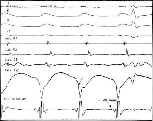
FIGURE 13-57 The role of unipolar recordings in mapping atrial tachycardia. Atrial tachycardia with high-degree block is shown with reference electrograms from the anterior and lateral right atrium and the lateral coronary sinus. The ablation of bipolar electrogram is shown on the bottom. The recorded electrograms precede the P wave by 40 msec. The ablation catheter is located in the superior posterior right atrium. The electrogram is characterized by a low-amplitude, slower moving fragmented signal, followed by a high-frequency large amplitude signal. The unipolar recording from the tip shows that the intrinsicoid deflection corresponds to the later high-frequency deflection. The low-frequency deflection is not associated with local activation in the unipolar recording suggesting that it is a far-field electrogram. In this case the site of origin was the right superior pulmonary artery.
Simultaneous multisite data acquisition can often help rapidly regionalize and localize the tachycardia origin. This is most commonly done with a basket catheter from which multiple recordings79 can demonstrate the site at which the tachycardia arises. More detailed mapping, however, is necessary to find the precise site to ablate. This is particularly useful if tachycardia episodes are short lived and/or cannot be reproducibly initiated by administration of catecholamines.
An important mapping technique involves pacing at sites of interest. If one is at the site of origin, pacing at this site should demonstrate a similar activation pattern to other sites being recorded in the right and left atrium as during the tachycardia.174 As described in Chapter 8 this method suggests that focal activation of the atrium from the site designated to be the site of origin is indeed the site of origin. This form of pace mapping is sometimes referred to as electrogram mapping, but merely is a more precise form of pace mapping (Fig. 13-58).
In most laboratories, electroanatomic mapping is used for atrial tachycardia. The precision in mapping that this
technique allows is much higher than with traditional techniques. One potential error that can be inadvertently introduced by this method, however, is the failure to consider additional sites when a site of earliest activation is automatically assigned in the chamber that is being mapped. Putative sites of earliest activation should precede the onset of the surface p wave, and can be vetted by analysis of unipolar recordings or pacing as described above. Regardless of where the site of origin of the tachycardia is, the target site usually shows fragmented electrical activity. An example of an atrial tachycardia arising from the os of the coronary sinus is shown in Figure 13-59. This long RP tachycardia was proven to be atrial tachycardia by the absence of retrograde conduction during ventricular pacing and persistence following adenosine-induced A-V block. The earliest site of atrial activity was at the lip of the coronary sinus and was associated with a multicomponent electrogram. RF ablation at that site terminated the tachycardia within 4 seconds. An example of atrial tachycardia arising from the inferolateral tricuspid annulus is shown in Figure 13-60. Earliest activity was recorded with a low-amplitude multicomponent electrogram 25 msec before the P wave. Electroanatomic mapping helped localize this to the tricuspid annulus where a single lesion terminated the arrhythmia. The W-shaped P wave observed in lead III in this patient is typical of P waves associated with tachycardias arising in this region. The electroanatomic mapping system is extremely important in preventing inadvertent A-V block while ablating tachycardias arising near the His bundle. An electroanatomic map of a para-Hisian atrial
tachycardia is shown in Figure 13-61. The map clearly delineated the His bundle and allowed for the ablation to be accurately delivered 1 cm superior to the proximal His bundle recording site where nearly instantaneous termination of the arrhythmia occurred. Of note we have seen three cases of atrial tachycardia mapped to just above the His bundle catheter which actually arose and were ablated from the noncoronary cusp in the aorta (Fig. 13-62). An electroanatomic map of a right atrial tachycardia arising near a scar, just below the superior vena cava is shown in Figure 13-63 and an analog map of an atrial tachycardia from the superior crista is shown in Figure 13-64. A Carto map of a focal atrial tachycardia at the mitral annulus is shown in Figure 13-65. In Figure 13-66 electroanatomic mapping demonstrated a small reentrant circuit near the mitral annulus adjacent to the septum. This tachycardia would have been totally missed had only right atrial mapping been performed. As one can see on the isochronic map in the right atrium, earliest activity (red) occurs in the region of the apex of the triangle of Koch adjacent to the His bundle recording site (orange dots). Ablation at this site may have potentially produced heart block, but not cure the tachycardia that was shown to arise in the left atrium as a small reentrant circuit adjacent to the mitral annulus. Reentrant excitation is shown by arrows as the color spreads from red to orange to yellow to green to blue and then purple adjacent to the initial site of red at the mitral annulus. The burgundy color marks the site of adjacent early and late activity. RF energy adjacent to the mitral annulus on the septum terminated this arrhythmia.
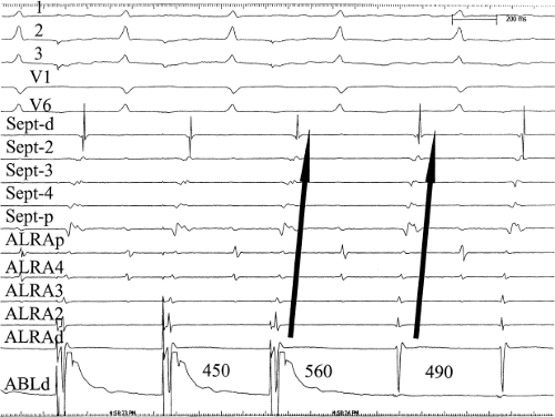 FIGURE 13-58 Use of paced activation mapping to confirm focal atrial tachycardia is occurring at the site from which the earliest map site is recorded. Five surface ECGs and decapolar catheters from the septum and anterolateral right atrium are shown with electrograms from the ablation catheter. On the right-hand part of the panel, the activation sequence during the tachycardia is seen. Note the tachycardia has a cycle length of 490 msec and the low-amplitude signal recorded in the ablation catheter precedes a W-shaped P wave by 35 msec. Pacing at this site at 450 msec (first three electrograms in the tracing) demonstrates a P-wave morphology and atrial activation sequence identical to that of the tachycardia. This confirms that this site was indeed the focus of the atrial tachycardia. See text for discussion. |
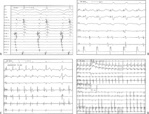 FIGURE 13-59 Ablation of atrial tachycardia at the os of the coronary sinus. A: Atrial tachycardia is present with the earliest activation seen at the os of the coronary sinus. Note that recordings from a decapolar catheter in the coronary sinus are earlier than the P-wave onset 3 and earlier than recordings from the His bundle catheter in the right atrium. Also note that the site of earliest activation has a markedly fractionated electrogram, typical of sites of earliest activity in atrial tachycardia. This electrogram precedes the P wave by 55 msec. B: Ventricular pacing during this tachycardia shows V-A dissociation confirming that this is an atrial tachycardia. C: Response of the tachycardia to adenosine: 6 mg of adenosine is given and the tachycardia slows minimally but continues with A-V block being present, again confirming the presence of atrial tachycardia. D: Ablation at the site of earliest activation terminates the tachycardia in approximately 4 seconds. This patient who had a tachycardia mediated cardiomyopathy demonstrated normalization of ventricular function within 3 months of the ablation. |
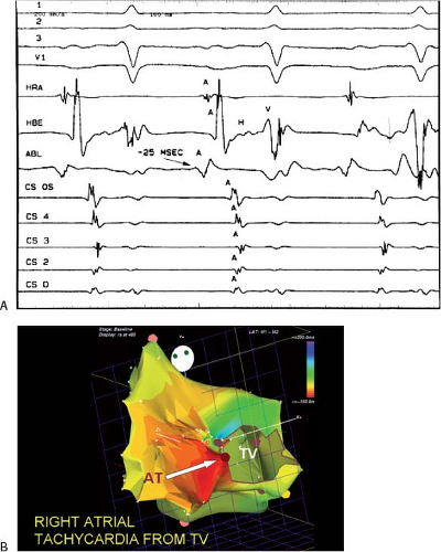 FIGURE 13-60 Role of electroanatomic mapping to guide ablation of focal tachycardia. A: Atrial tachycardia is present. Note the morphology of the P wave has a W-like configuration. The earliest activation was shown to be recorded in the inferolateral right atrium at the tricuspid annulus. B: Electroanatomical mapping of the atrial tachycardia shown on top reveals earliest activation at the lateral tricuspid annulus. There is sequential spread to the rest of the atrium. Ablation at the earliest site (red-brown dot) at which the white arrow is pointed, was successful. |
The success rate for ablation of focal paroxysmal atrial tachycardia is highly variable and depends on the expertise of the investigator and the cause of the atrial arrhythmia. When atrial tachycardias are present incessantly the success rate approaches 90%, although there is a recurrence rate as high as 25%.169,170,171,172,173,174,175 The early NASPE 1998 registry reports a success rate of 70% and a complication rate of 3%.116 These success rates do not truly reflect the difficulty of atrial tachycardia ablation. Since these arrhythmias may not be reliably present
at the time of the electrophysiology study, a true success rate on an intention to treat basis cannot be determined. Clearly it would be lower than the 90% or more success rate of persistent tachycardias. Thus, the mechanism of the focal arrhythmia also influences outcome.176
at the time of the electrophysiology study, a true success rate on an intention to treat basis cannot be determined. Clearly it would be lower than the 90% or more success rate of persistent tachycardias. Thus, the mechanism of the focal arrhythmia also influences outcome.176
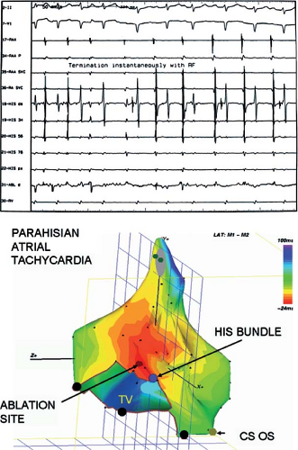 FIGURE 13-61 Use of electroanatomic mapping to prevent inadvertent heart block during ablation of an atrial tachycardia, just adjacent to the His bundle. An electroanatomic map in a patient with atrial tachycardia occurring 5 mm superior to the His bundle is shown in the bottom panel. The site of earliest activation is denoted by the brown dot. The site of the His bundle is shown by blue. Three-msec isochrones are shown in this tracing. The catheter was able to be positioned above the His bundle safely and RF energy delivered at this site. Application of RF energy at this site immediately terminated the tachycardia (top panel). |
In patients in whom ablation fails and pharmacologic therapy cannot be appropriately applied, two potential therapeutic options are available. One is to ablate the A-V junction and implant a pacemaker. The other is to surgically resect or isolate the tachycardia. Success of surgery depends on being able to map the tachycardia at the time of surgery. In the absence of doing this, procedures such as a left atrial isolation can be performed if the tachycardia is localized to the specific atrium (Fig. 13-67). We operated on a patient with a tumor-related right atrial tachycardia that was mapped to the limbus of the fossa ovalis in the laboratory in the preablation era. This tachycardia could not be induced in the operating room, but mapping of isolated frequent APCs induced by catecholamines provided enough information to localize the rhythm and ablate it (Fig. 13-68). Tachycardias that cannot be ablated and that have been shown to arise in the left or right atrial appendage can be cured by surgical removal of the appendage. This is certainly a smaller procedure than isolation of the left atrium and could be performed through a minithoracotomy or thorascopy
as long as the tachycardia has been mapped to the tip of the left atrial appendage.
as long as the tachycardia has been mapped to the tip of the left atrial appendage.
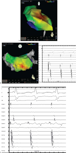 FIGURE 13-62 Ablation of a para-Hisian atrial tachycardia from the noncoronary sinus of Valsalva. In panel A, an electroanatomic map of the right atrium during atrial tachycardia is shown. Note the broad area of earliest atrial activation just superior to the His bundle recording (denoted by the yellow icon); this sort of diffuse early activation is typical when mapping a chamber adjacent to the actual site of tachycardia origin. An activation map of the left atrium is shown in panel B. This registers a discreet early site, but pacing from this site causes subtle changes in the morphologies of the atrial electrograms compared to those recorded in tachycardia. Mapping of the noncoronary cusp (panel C) demonstrates a much earlier signal, and ablation at this site resulted in elimination of the atrial tachycardia without effecting A-V conduction. |
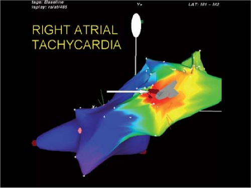 FIGURE 13-63 Scar-related atrial tachycardia from the superior and posterolateral right atrium. Electroanatomic mapping of an atrial tachycardia is shown in this figure. Scar is shown in gray and bright red is the site of earliest atrial activation. The red-brown dots (arrow) are the site of successful ablation. |
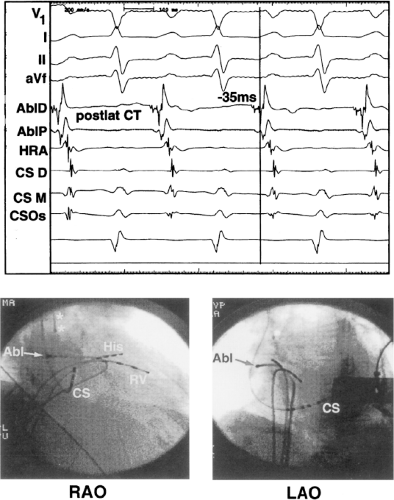 FIGURE 13-64 Analog recordings and fluoroscopic images of catheter and ablation site shown in Figure 13-63. Analog records show fractionated earliest site 35 msec prior to the P wave. Fluoroscopic images of catheter position are shown on the bottom. |
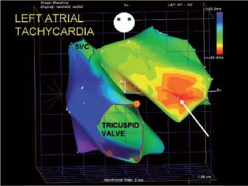 FIGURE 13-65 Electroanatomic map of focal atrial tachycardia just above the mitral annulus. Electroanatomic mapping of an atrial tachycardia is shown with earliest activation in red and latest activation in purple at 5-msec isochronal steps. Note that the right atrium is late and it is activated in blues and purples. The earliest site of atrial activation (white arrow) is shown just superior to the mitral annulus in red and was a site at which a single RF application ablated the tachycardia. |
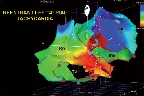 FIGURE 13-66 Electroanatomic mapping demonstrating small left atrial reentrant tachycardia. The mapping of both the right and left atrium and 5-msec isochronal steps is shown in this figure. Earliest activation is seen in red, latest activation is seen in purple. The point at which earliest and latest activation meet is shown in dark burgundy. The arrows demonstrate reentrant excitation in this small area above the mitral annulus. A single lesion between the burgundy area and the mitral annulus terminated the tachycardia and prevented its reinitiation. If only right atrial activation were used, a focal tachycardia on the septum might have been suggested, leading to failed RF application and a potential for heart block. |
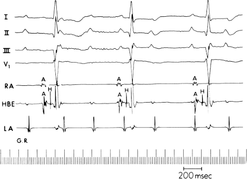 FIGURE 13-67 Isolation of atrium to manage atrial tachycardia. Recordings, from the top down, are surface ECG leads I to III, V1, bipolar catheter recordings of the right atrium (RA) and the His bundle, and a bipolar recording obtained by permanent electrodes sutured to the left atrial appendage (LA). The right and left atria are dissociated. Right atrial activity proceeds from the catheter positioned in the high RA to the atrial septum as recorded on the His bundle catheter, followed by conduction to the ventricle. An irregular left atrial tachycardia is present, which fails to propagate to either the right atrium or to the ventricles. (From Gallagher JJ, Cox JL, German LD, Kasell JH. Nonpharmacologic treatment of supraventricular tachycardia. In: Josephson MD, Wellens HJJ, eds. Tachycardias: mechanisms, diagnosis, treatment. Philadelphia, PA: Lea & Febiger, 1984:271.) |
Ablation of Atrial Flutter and other Macroreentrant Atrial Arrhythmias
Typical atrial flutters are macroreentrant circuits involving the right atrium and may rotate in a clockwise or counterclockwise fashion.169,170,175,177,178 The circuit has the tricuspid annulus as its anterior boundary with posterior boundaries being the coronary sinus inferior vena cava, crista terminalis, and fossa ovalis.172,175,177,178,179 These boundaries are obviously a combination of anatomic structures and the functional consequences of propagation through those structures. Because typical flutters must proceed through an isthmus created by the tricuspid annulus, coronary sinus, and inferior vena cava, these flutters are now more appropriately termed “isthmus-dependent” flutter. Other macroreentrant circuits in either the right or left atrium are considered atypical flutters. The vast majority of clinically encountered atrial flutters are isthmus-dependent flutters; however, atypical flutters, which commonly complicate ablation therapy for atrial fibrillation, are certainly becoming increasingly frequent. Isthmus-dependent flutters frequently coexist with atrial fibrillation.
As described in detail in Chapter 9, isthmus-dependent flutter can circulate around the tricuspid valve in a clockwise or counterclockwise fashion (Fig. 13-69). Although typical electrocardiographic patterns have been described for isthmus-dependent flutter, these ECG characteristics are not always present. We have reviewed 200 consecutive cases of isthmus-dependent flutter in which the distal and/or proximal coronary sinus activation was recorded along with right atrial activation.180 Counterclockwise flutter (the more common variety) may be characterized by pure negative deflections in the inferior leads, negative followed by positive deflections that are approximately of equal size, or a small negative deflection followed by a positive deflection of greater amplitude. These three varieties coexist with tall positive P waves, smaller positive P waves, or biphasic P waves in V1, respectively. The degree to which positivity in the inferior leads is present appears to be related to the coexistence of heart disease and an enlarged left atrium. It is therefore apparent that propagation of atrial flutter to and through the left atrium is a major determinant of the flutter-wave morphology. This may lead to misleading and confusing interpretations of the electrocardiogram. Counterclockwise flutter can be mistaken for clockwise flutter, which generally has positive deflections in the inferior leads. The major difference is that in counterclockwise, isthmus-dependent flutter there is always a negative deflection that precedes the positive deflection. With clockwise flutter, there is a notching of the positive deflection in the middle of the flutter wave. Thus, despite the fact that isthmus-dependent flutter is a right atrial phenomenon, propagation to and through the left atrium determines its electrocardiographic appearance. As described in detail in Chapter 9, proof that one is dealing with isthmus-dependent flutter involves the use of pacing techniques to demonstrate the mechanism of the flutter. When pacing from components of the flutter circuit, the return cycle equals the flutter cycle length and the wavefront of activation is the same as that during flutter except for all amounts of fusion (caused by antidromic capture). Pacing from the isthmus shows no fusion of intra-atrial recordings because collision of wavefronts occurs within this slowly conducting, protected region of the circuit. Thus pacing from the isthmus shows a return cycle equal to the flutter cycle length, a paced atrial morphology equal to the flutter morphology, and a stimulus to coronary os electrogram equal to the spontaneous electrogram recorded by the pacing catheter and the coronary sinus electrogram during flutter. The response to entrainment from sites inside and outside the circuit is discussed in Chapter 9.
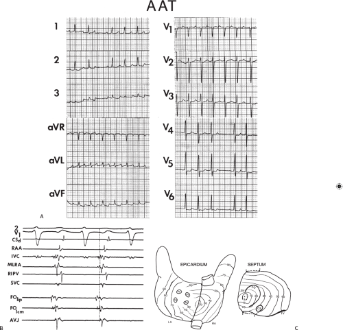 FIGURE 13-68 Surgical cure of right atrial tachycardia. A: The 12-lead ECG of atrial tachycardia. B: Selective sites from the preoperative catheter map. C: Intraoperative epicardial and septal map. Earliest activity was from the posterior tip of the fossa ovalis (FO). AAT, automatic atrial tachycardia; MLRA, mid-lateral right atrium; RIPV, right inferior pulmonary vein. |
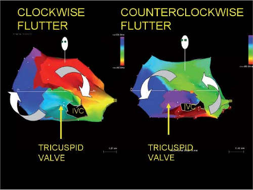 FIGURE 13-69 Electroanatomic mapping of isthmus-dependent flutter. As described in Chapter 9, isthmus-dependent flutter can circulate around the tricuspid valve in a clockwise or counterclockwise direction as seen in the left anterior view. These two distinct patterns of activation are shown in the electroanatomic maps in this tracing. Activation proceeds from red to orange to yellow to green to a variety of blues to purple. The joining of the latest site with the earliest site is shown in dark burgundy. These activation maps are made in approximately 5-msec isochrones and clearly demonstrate the two types of rotation around the tricuspid annulus. |
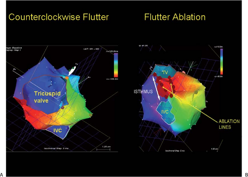 FIGURE 13-70 Utility of electroanatomic mapping in ablating atrial flutter. A: Counterclockwise flutter is shown around the tricuspid valve. B: Using a posterior view, the isthmus between the tricuspid valve and inferior vena cava can be seen and linear lines of ablation can be drawn between the tricuspid valve and IVC. The arrow defines the isthmus that must be ablated. TV, tricuspid valve. IVC, inferior vena cava. |
Electroanatomic mapping can be used in atrial flutter ablation (Fig. 13-70). Mapping systems allow one to rotate the heart to see the tricuspid-inferior vena cava isthmus and allows one to place RF lesions in a linear fashion between the tricuspid valve and inferior vena cava. We usually perform ablation during flutter. Invariably flutter is terminated during application of a critical lesion at the site of the ablation catheter (Fig. 13-71). Since termination of the flutter does not necessarily mean that the line is complete, continued ablation is performed during coronary sinus pacing. When true block has not been accomplished across the isthmus, pacing in the CS will demonstrate opposite wavefronts colliding in the lateral right atrium with one wavefront going clockwise through the unblocked isthmus and another wavefront going counterclockwise around the crista terminalis. This is what is seen prior to ablation (Fig. 13-72). When ablation of the tricuspid annulus is complete, clockwise propagation through the isthmus is not possible and the entire tricuspid annulus is activated in a counterclockwise direction (Fig. 13-72). This can be verified by the Carto system as demonstrated in Figure 13-73. Following the ablation, pacing at the coronary sinus os demonstrates block of the wavefront at the line of ablation in the isthmus with counterclockwise activation around the tricuspid annulus to block in that direction. To assure success, bidirectional block must also be shown.175,181,182,183 In this instance, pacing from just lateral to the site of ablation will produce block toward the CS electrogram and activation of the tricuspid annulus only in a clockwise fashion in addition to block in the opposite direction as described above (Fig. 13-74). Electroanatomic mapping systems are also useful because they provide information about the voltage characteristics of the tissue involved in the isthmus. The lower the voltage the easier it is to achieve block in the tissue. Thus one might chose a path in the isthmus that is slightly longer through low-voltage tissue than a shorter route through high-voltage tissue, which represents a thicker atrial myocardium. Other appropriate endpoints of cavotricuspid isthmus ablation include widely split double potentials along the entire ablation line (isoelectric intervals of ≥110 msec),184 absence of local atrial activity (electrograms <0.05 mV) along the ablation line or the reversal of unipolar electrogram polarity on two closely spaced electrodes, on either side of the ablation line during CS pacing.185
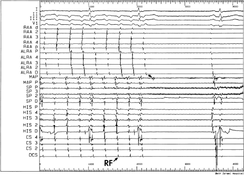 FIGURE 13-71 Termination of isthmus-dependent flutter during RF application. Isthmus-dependent, counterclockwise flutter is shown on the left. Electrograms from the right atrial appendage (RAA), the anterolateral right atrium around the tricuspid annulus (LARA) with the distal (d) ALRA being misplaced at the lateral tricuspid annulus at the lateral border of the isthmus. Slow pathway proximal to distal. A decapolar catheter in the His bundle recording site and an octapolar catheter in the coronary sinus. During the formation of a linear lesion, atrial flutter terminates with block in the mapping/ablation catheter, which is positioned in the center of the isthmus. |
Some investigators prefer to ablate between the tricuspid annulus and the coronary sinus since it is the shortest path. This frequently fails, I believe, because the impulse can propagate through the Eustachian ridge (albeit slowly) to go around the IVC and produce a lower loop reentry. Analysis of Carto maps of atrial flutter frequently demonstrates simultaneous activation across the Eustachian ridge and around the IVC to produce a lower loop of reentrant excitation that meets the loop going counterclockwise around the tricuspid annulus in a figure-of-eight fashion (Fig. 13-75). This is also graphically shown using a basket catheter in Figure 13-76. Both the lower loop and upper loop can be simultaneously entrained. While the Eustachian ridge is believed to be a fixed obstacle that produces block because of the observation of double potentials that are often seen on either side of it, this may not in fact represent true block, but a very slowly propagating wavefront.186 In fact, the ability to slowly conduct across the Eustachian ridge may be responsible for lower loop reentry that follows inadequate ablation of the isthmus because of placing ablation lines too medially, such that propagation across the Eustachian ridge is still possible. Ablation along the Eustachian ridge or between the tricuspid annulus and the
inferior vena cava will eliminate this rhythm as well. Lower loop reentry has been described by Cheng et al.187 and may not be as uncommon as previously thought.
inferior vena cava will eliminate this rhythm as well. Lower loop reentry has been described by Cheng et al.187 and may not be as uncommon as previously thought.
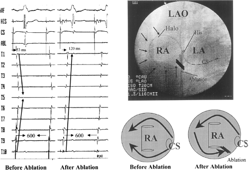 FIGURE 13-72 Demonstration of block across the isthmus using coronary sinus pacing. In the top right is a fluoroscopic image showing a halo catheter positioned around the tricuspid annulus, the coronary sinus catheter, the His catheter, and the ablation catheter. Prior to and after ablation, the activation patterns around the tricuspid annulus using a halo catheter are shown on the left. Prior to ablation, pacing the coronary sinus demonstrates both superior and inferior wavefronts around the tricuspid annulus (far left panel). After ablation, a line of block appears to be created in the isthmus and activation of the tricuspid annulus only goes over the superior route (middle panel). This is schematically shown in the lower right-hand part of the figure. |
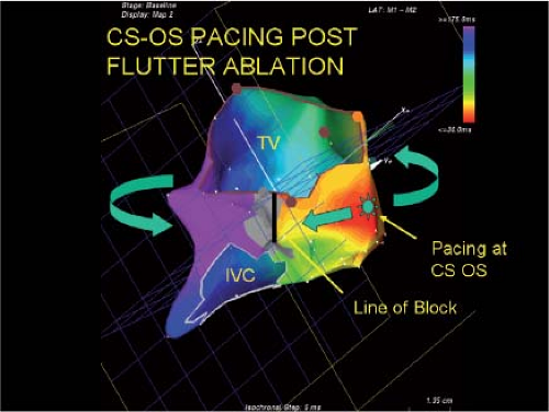 FIGURE 13-73 Use of electroanatomic mapping to demonstrate the line of block during coronary sinus pacing. During coronary sinus pacing following ablation, one sees a complete line of block with no activation proceeding across that line of block in either direction. Activation of the entire tricuspid ring remains counterclockwise except for the small portion that is situated between the pacing site and the line of block. The electroanatomic mapping system allows detection of any breaks in the line of block, which may not be seen using the halo catheter or any single catheter in a fixed position. |
Intraisthmus reentry, as described in Chapter 9, involves a circuit around the coronary sinus, bordered by the tricuspid annulus and the Eustachian ridge.188 This may occur spontaneously or after the creation of a lateral cavotricuspid isthmus ablation line, as it utilizes only the septal portion of the isthmus, and may even be facilitated by an isthmus ablation. These arrhythmias are characterized by negative flutter waves in the inferior leads and a short (<100 msec) “trans-isthmus” conduction time. Successful ablation of intraisthmus reentry involves creation of a line of block from the CS os to the tricuspid annulus and from the CS os across the Eustachian ridge to the IVC (Figs. 13-77 and 13-78). While both ablation lines may not be absolutely necessary to treat this circuit, the additional line from the CS os to the IVC prevents the development of lower loop reentry as described above.
Contemporary results for ablation of typical flutter demonstrate a high degree of efficacy; a recent meta-analysis documented an acute success rate of 94%.189 More complete adoption of large tip catheters or irrigated RF ablation has increased acute success and reduced the risk of recurrence.
One factor that can greatly complicate cavotricuspid isthmus ablation is abnormal anatomy, atrial pouches (which are more frequent in the medial isthmus) or thick pectinate ridges (more frequent in the lateral isthmus), or a prominent Eustachian ridge.190 Although certainly not necessary for routine use, intracardiac echocardiography can be useful in difficult cases to visualize the underlying anatomy (Fig. 13-79).
One factor that can greatly complicate cavotricuspid isthmus ablation is abnormal anatomy, atrial pouches (which are more frequent in the medial isthmus) or thick pectinate ridges (more frequent in the lateral isthmus), or a prominent Eustachian ridge.190 Although certainly not necessary for routine use, intracardiac echocardiography can be useful in difficult cases to visualize the underlying anatomy (Fig. 13-79).
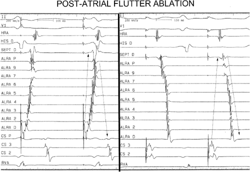 FIGURE 13-74 Demonstration of bidirectional block. To assure success of flutter ablation bidirectional block should be demonstrated. This is necessary because occasionally one can demonstrate complete block in one direction but not in another. Pacing on either side of the To ablation line demonstrates that activation around the tricuspid annulus proceeds only in the direction away from the line. In the panel on the left, pacing in the lateral isthmus shows a clockwise activation around the tricuspid ring. Conversely, pacing the proximal coronary sinus demonstrates a clockwise pattern of activation around the tricuspid annulus. |
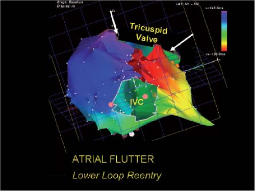 FIGURE 13-75 Demonstration of a lower loop of reentry using the electroanatomic mapping system. Counterclockwise flutter is shown by analyzing the activation sequence around the tricuspid annulus. However, activation around the IVC, also demonstrates reentrant excitation. As in other electroanatomic maps, the earliest site of activation is arbitrarily shown in red with sequential activation to orange, yellows, greens, blues, and purples. A dark burgundy line demonstrates a line bordering the earliest and latest activation. Notice the densest isochrones appear in the tricuspid-inferior vena cava isthmus. |
If bidirectional block can be demonstrated, the incidence of recurrent atrial flutter is less than 10%. In our laboratory it is 6%. Failure to demonstrate bidirectional block, however, is associated with a 20% recurrence rate of flutter. When recurrence occurs, noncontact mapping67 or electroanatomic mapping has been very useful in defining the “leak” in the prior linear lesions. This facilitates sealing the leak and creating bidirectional block. Natale et al.191 have demonstrated that a primary ablation approach to flutter is superior to pharmacologic approaches. Moreover, the incidence of subsequent atrial fibrillation (a common spontaneous accompaniment to atrial flutter) is less, in short-term follow-up (∼1 year), than when pharmacologic therapy is used,192 primarily in the absence of heart disease. The incidence of atrial fibrillation appearing after atrial flutter ablation in patients with normal hearts and atrial flutter as the only documented arrhythmia, is in the order of 10% at 1 year, whereas in the presence of organic heart disease, in particular hypertension, and heart failure, atrial fibrillation occurs in >80% in 3-year follow-up. Patients with concomitant atrial fibrillation can be recognized by ECG (atypical flutter patterns described above) or by echocardiographic enlarged left atria. This is not surprising since structural heart disease is a substrate for atrial fibrillation. In my opinion, patients who have flutter should undergo ablation as a primary procedure. In addition, in patients who have a history of flutter and fibrillation, the incidence of fibrillation episodes may be diminished by a flutter ablation. This suggests that flutter is involved in either the initiation and/or perpetuation of atrial fibrillation in a certain percentage of patients. This is another reason to consider flutter ablation in anyone who has this rhythm documented.
Left atrial flutters are more difficult to ablate, primarily because they are difficult to document. Electroanatomic mapping has been useful in this regard.193 Many left atrial flutters
circulate around the mitral annulus with the pulmonary veins and fossa ovalis as posterior boundaries.193 Scars from prior surgical procedures can provide obstacles that lead to atrial tachycardias with large excitable gaps. These are similar electrophysiologically to isthmus-dependent flutter. They can be caused by routine atriotomy incisions, postcardiac transplant, or following correction to congenital heart disease. Detailed mapping shows double potentials and low voltages in the area of incision. Electroanatomic mapping is invaluable in localizing “gaps” in the “scar” line through which the impulse can propagate and produce a macroreentrant circuit. Focal ablation at these gaps can cure the rhythm. An example is shown in Figure 13-80. The voltage map and double potentials define the “scar” region. Activation is possible where a small gap near the superior border of the “scar” (panel B) is. Ablation at this site cured the tachycardia. I believe these gaps are caused by the pressure of the “clamp” superior and/or inferior to the actual atriotomy scar.
circulate around the mitral annulus with the pulmonary veins and fossa ovalis as posterior boundaries.193 Scars from prior surgical procedures can provide obstacles that lead to atrial tachycardias with large excitable gaps. These are similar electrophysiologically to isthmus-dependent flutter. They can be caused by routine atriotomy incisions, postcardiac transplant, or following correction to congenital heart disease. Detailed mapping shows double potentials and low voltages in the area of incision. Electroanatomic mapping is invaluable in localizing “gaps” in the “scar” line through which the impulse can propagate and produce a macroreentrant circuit. Focal ablation at these gaps can cure the rhythm. An example is shown in Figure 13-80. The voltage map and double potentials define the “scar” region. Activation is possible where a small gap near the superior border of the “scar” (panel B) is. Ablation at this site cured the tachycardia. I believe these gaps are caused by the pressure of the “clamp” superior and/or inferior to the actual atriotomy scar.
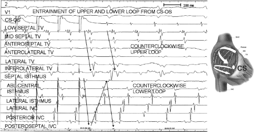 FIGURE 13-76 Demonstration of lower and upper loop reentry simultaneously shown using a basket catheter. Activation around the tricuspid annulus (TV), and the IVC are shown during pacing of the coronary sinus. During atrial flutter, coronary sinus pacing entrains both the activation loop around the tricuspid annulus and the counterclockwise loop around the inferior vena cava. Both loops share the common isthmus. The loops are schematically shown in the figure on the right. |
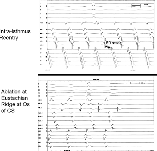 FIGURE 13-77 The requirement of ablation across the Eustachian ridge to treat intraisthmus reentry. Intraisthmus reentry is shown on top with a typically short intraisthmus conduction time. Termination of the arrhythmia occurs with radiofrequency energy delivered along the coronary sinus os Eustachian ridge area. See text for explanation. |
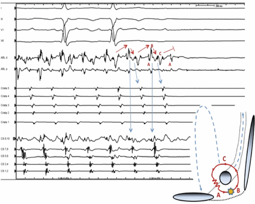 FIGURE 13-78 Intraisthmus reentry. Four surface leads and intracardiac recordings from the ablation catheter, crista (right atrial) and coronary sinus decapolar catheters are shown during on-going tachycardia which is terminated by ablation between the coronary sinus and the IVC (denoted by the star on the schema). Note the extremely complex nature of the ABL catheter recording, which different components reflecting activation of different areas surrounding the coronary sinus, as explained in the schema (inset). |
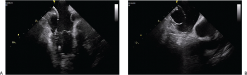 FIGURE 13-79 The use of intracardiac echocardiography (ICE) for tricuspid isthmus ablation. An ICE imaging frame is shown during tricuspid isthmus ablation in a patient with a prominent Eustachian ridge (arrow). In (A), the ablation catheter is positioned across the tricuspid valve (TV); simple pull back of the catheter would result in failure to contact the portion of isthmus close to the IVC because of “guarding” by the Eustachian ridge. ICE imaging allows recognition of this anatomic variant, and appropriate positioning of the ablation catheter (B). (Courtesy of Luis Saenz, MD.) |
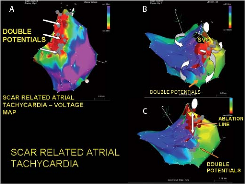 FIGURE 13-80 Ablation of scar-related atrial flutter/tachycardia using electroanatomic mapping. A: A bipolar voltage map is shown during sinus rhythm in a patient with an atrial tachycardia (250 msec), following open heart surgery. Voltages less than 0.2 mV are shown in red and those over 1.5 mV are shown in purple. 1.5 mV is considered normal. Double potentials are shown with gray dots. The low-voltage and double potentials denote signs of scar tissue. B: Activation mapping during a tachycardia is shown. One can see reentrant excitation with activation proceeding through an isthmus bordered by two of the double potentials. The arrows describe the figure-of-eight reentrant circuit. C: Ablation along the line of double potentials completes a line of block (arrow) between the superior vena cava and the isthmus through which the circuit participated. This terminated the tachycardia and eliminated its reinduction. |
When large continuous anatomic barriers produce macroreentrant tachycardias, lines of RF incisions must connect the causal anatomic boundary to another boundary (i.e., tricuspid annulus).
Focal arrhythmias “masquerading” as atrial flutter may also exist in the substrate of prior atrial scar. An example is shown in Figure 13-81 from a patient with prior right atrial incision for surgical correction of congenital heart disease who had a focal tachycardia (proven by pacing techniques) which was eliminated with a single RF lesion.
Atypical atrial flutters are also common after ablation of atrial fibrillation. In addition, as contemporary ablation strategies have focused on ablation more proximally within the atrium (antral ablation), the incidence of postprocedure flutters has increased. The most frequent atrial flutters following AF ablation are mitral isthmus–dependent and roof-dependent flutters. Importantly, these often coexist, sometimes at subtly different cycle lengths (Fig. 13-82). Little controversy exists regarding the treatment of roof-dependent flutter. This is safely and effectively accomplished by a linear lesion at the superior left atrium, connecting the right and left PV antral isolation lesions. In contrast, several different approaches have been advocated for mitral isthmus–dependent flutter. The traditional approach was a linear lesion from the mitral annulus to the left inferior pulmonary vein. The advantage to this strategy was that the line was short, and relatively easy to interrogate for block following delivery. The disadvantages were the difficult in accomplishing block in this line (thought secondary to cooling effects of the adjacent great cardiac vein), a substantial recurrence rate and possible damage to the left circumflex artery. More recently, an anterior line, connecting the anterior mitral annulus to the right superior pulmonary vein has been suggested (Fig. 13-83). The advantage to this strategy is that it avoids the great vessels in the A-V groove; however, it is a long linear lesion and has been reported to affect the arterial supply to the sinus node when it originates from the
circumflex artery. As demonstrated by the Bordeaux group, incomplete linear lesions in the atrium can be proarrhythmic; this necessitates careful investigation of the line to assure that conduction block has been achieved (Fig. 13-84).194,195
circumflex artery. As demonstrated by the Bordeaux group, incomplete linear lesions in the atrium can be proarrhythmic; this necessitates careful investigation of the line to assure that conduction block has been achieved (Fig. 13-84).194,195
Stay updated, free articles. Join our Telegram channel

Full access? Get Clinical Tree


