Radiofrequency catheter ablation has transformed the treatment of many rhythm disturbances, especially those of supraventricular origin. For many common arrhythmias it is not just another therapeutic option but first-line treatment, offering a cure and obviating the need for antiarrhythmic drugs. Success rates well over 90% are being widely achieved at very low risk. The purpose of this chapter is to illustrate briefly some of the main applications of catheter ablation and to provide an understanding, for those who refer patients for ablation, as to how sites for ablation are targeted.
Procedure
The procedure is usually carried out under local anaesthesia with intravenous sedation. The sequence of cardiac activation during normal and abnormal rhythms is studied by recording electrograms from various intracardiac sites using multipolar catheter electrodes introduced via percutaneous puncture of the femoral vein and, if necessary, the femoral artery. The electrodes also facilitate introduction of pacing stimuli that can initiate and terminate tachycardias.
Mapping the sequence of activation during normal, paced rhythms, and during tachycardia, enables location of the re-entrant circuit or focus causing the arrhythmia. Radiofrequency energy, which is high-frequency alternating current, is delivered via a special catheter electrode. This has a deflectable end, enabling the tip to be precisely positioned at the target site. Radiofrequency energy is delivered for 30–120 s. The endocardium in contact with the tip and the myocardium beneath is heated to 50–70 °C and is thereby coagulated. Surrounding myocardium is not damaged. Radiofrequency energy delivery via an electrode irrigated with saline can result in a larger, deeper lesion by preventing coagulum developing at the catheter tip and is useful in difficult cases and in ablation for atrial flutter.
Cryothermy is being evaluated as an alternative energy source.
Normal sinus rhythm
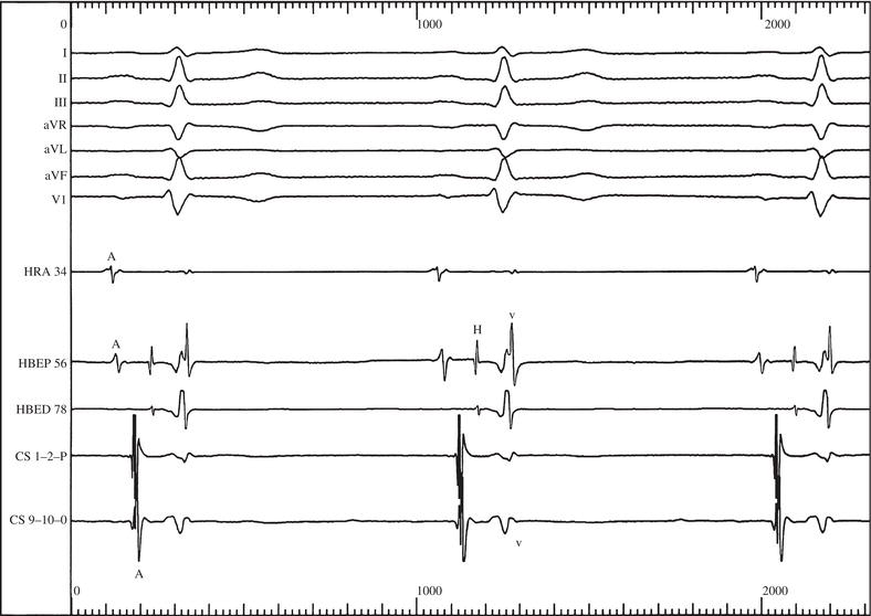
Figure 25.1 shows typical findings during normal sinus rhythm. Recordings are made at a paper speed of at least 100 mm/s. Below the six surface ECG leads are recordings from three intracardiac sites: high right atrium, tricuspid valve and the coronary sinus.
High right atrial electrogram
An electrode positioned in the high right atrium is close to the sinus node. It records the earliest atrial activity during each cardiac cycle. It coincides with the onset of the P wave seen on the surface ECG.
Figure 25.1 Sinus rhythm. Six surface ECGs, and intracardiac ECGs from the high right atrium (HRA), from the His bundle (HBEP = proximal, HBED = distal) and coronary sinus (CS P = proximal, CS D = distal). A, H and V = atrial, His bundle and ventricular electrograms, respectively).
His bundle electrogram
The His bundle electrogram is recorded by positioning an electrode across the tricuspid valve. Three waves can be seen:
- The A wave due to activation of the adjacent low right atrium.
- The H wave: the electrogram resulting from activation of the His bundle. The interval between A and H waves indicates the conduction time through the AV node.
- The V wave, which is the ventricular electrogram. It corresponds to the QRS complex on the surface ECG. The HV interval indicates the time of transmission by the His bundle and bundle branches from the AV node to the ventricular myocardium. It is normally 35–55 ms. Often, as in Figure 25.1, electrograms are recorded from two pairs of electrodes on the multipolar catheter across the tricuspid valve so that proximal and distal His bundle electrograms can be obtained.
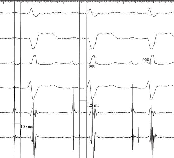
Figure 25.2 shows a markedly prolonged HV interval in a patient with bifascicular block.
Coronary sinus electrograms
The coronary sinus runs in the groove between the left atrium and left ventricle. Activity from both left atrium and left ventricle can be recorded.
In Figure 25.1, a large left atrial electrogram can be seen, which is followed by a smaller wave resulting from left ventricular activity.
Mapping
Figure 25.1 provides a simple example of how the path of an activating impulse can be ‘mapped’. During normal sinus rhythm, it shows how the atrial impulse originates in the high right atrium (i.e. close to the sinus node), passes to the low right atrium, near to the AV node, and then to the left atrium as recorded by the coronary sinus electrodes. Following atrial activation, His bundle and then ventricular activation occur.
Figure 25.2 Surface leads I, II, V1 and V6 together with a bundle of His electrogram (bottom trace) in a patient with bifascicular block and a long PR interval. The AH interval (100 ms) is normal but the HV interval (125 ms) is markedly prolonged.
Wolff–Parkinson–White syndrome
An accessory pathway is located by identifying the site of earliest ventricular activation during sinus rhythm, for that must be the site where the accessory pathway connects with ventricular myocardium. An electrogram at this site will precede the onset of the delta wave in the surface ECG (Figure 25.3). Sometimes, it is possible to actually demonstrate an accessory pathway potential (Figure 25.4).
Figure 25.5 shows how the surface ECG and electrogram at the site of radiofrequency delivery change as the accessory pathway is ablated by radiofrequency energy.
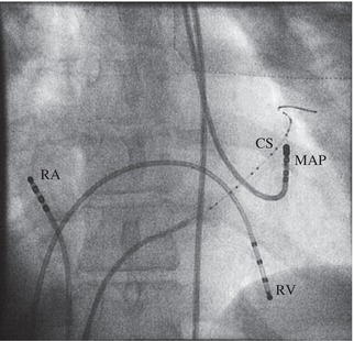
Left-sided pathways are ablated by introducing a catheter into the left ventricle via the femoral artery (Figure 25.6) or by transseptal puncture via the femoral vein, and positioning its tip across the mitral valve ring. Free right wall accessory pathways are ablated by introducing a catheter from the femoral vein and positioning across the tricuspid valve ring. Posteroseptal and anteroseptal pathways are also ablated by a catheter in the right ventricle. Posteroseptal pathways are found near the mouth of the coronary sinus. Anteroseptal pathways are located close to the bundle of His.
Figure 25.3 Wolff–Parkinson–White syndrome. The vertical line marks the onset of the delta wave on the surface ECG. The tip of the mapping electrode has been positioned at the site of successful ablation. Both A and V waves can be seen in the mapping electrogram. The V wave precedes the onset of the surface ECG delta wave by 25 ms.
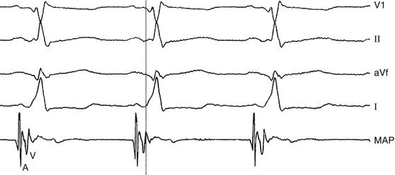
Figure 25.4 Wolff–Parkinson–White syndrome during atrial fibrillation. Surface leads I, II, AVF and V1. The arrow indicates a potential arising from an accessory pathway, recorded via the mapping electrode, which precedes the onset of the delta wave on the surface ECG.
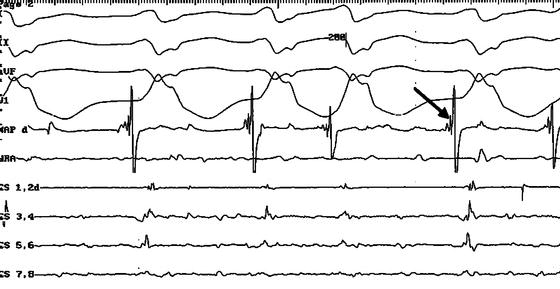
Figure 25.5 Wolff–Parkinson–White syndrome. The electrogram from the mapping electrode can be seen beneath two surface ECGs. The vertical line demonstrates that before ablation, ventricular activity recorded by the mapping electrode precedes the onset of the surface ECG delta wave. Radiofrequency energy is delivered after the first two beats and interrupts accessory pathway conduction. After ablation, the delta wave disappears and ventricular activity in the mapping electrogram succeeds rather than precedes the surface ECG QRS complex.
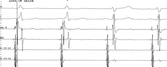
Figure 25.6 Ablation of left-sided accessory pathway. Electrodes are positioned in the right atrium (RA) and right ventricle (RV). There is a multipolar electrode in the coronary sinus (CS). The mapping electrode (MAP) has been introduced via the femoral artery, passed through the aortic valve and positioned across the mitral valve ring.
There is a risk (1–4%) that anteroseptal and, to a lesser extent, posteroseptal accessory pathway ablation might cause complete heart block and the need for long-term pacing.
Sometimes, ‘T wave memory’ following successful posteroseptal ablation causes unnecessary concern (Figure 25.7).
Concealed accessory pathways
Stay updated, free articles. Join our Telegram channel

Full access? Get Clinical Tree


