Cardiac Monitors
Purpose of ECG monitoring
The electrocardiogram (ECG) is a recording of the electrical activity of the heart. The ECG records two basic electrical processes:
▪ Depolarization — the spread of the electrical stimulus through the heart muscle, producing the P wave from the atria and the QRS complex from the ventricles.
▪ Repolarization — the recovery of the stimulated muscle to the resting state, producing the ST segment, the T wave, and the U wave.
The depolarization-repolarization process produces electrical currents that are transmitted to the surface of the body. This electrical activity is detected by electrodes attached to the skin. After the electric current is detected, it’s amplified, displayed on a monitor screen (oscilloscope), and recorded on ECG graph paper as waves and complexes. The waveforms can then be analyzed in a systematic manner and the “cardiac rhythm” identified.
Bedside monitoring allows continuous observation of the heart’s electrical activity and is used to identify arrhythmias (disturbances in rate, rhythm, or conduction), evaluate pacemaker function, and evaluate the response to medications (for example, antiarrhythmics). Continuous cardiac monitoring is useful in monitoring patients in critical care units, cardiac stepdown units, surgery suites, outpatient surgery departments, emergency departments, and postanesthesia recovery units.
Types of ECG monitoring
There are two types of ECG monitoring: hardwire and telemetry. With hardwire monitoring (bedside monitoring), electrode pads (conductive gel discs) are placed on the patient’s chest and attached to a lead-cable system and then connected to a monitor at the bedside. With telemetry monitoring (portable monitoring), electrode pads are attached to the patient’s chest and connected to leads that are attached to a portable monitor transmitter.
▪ Hardwire monitoring — Hardwire monitoring uses either a five-leadwire system or a three-leadwire system.
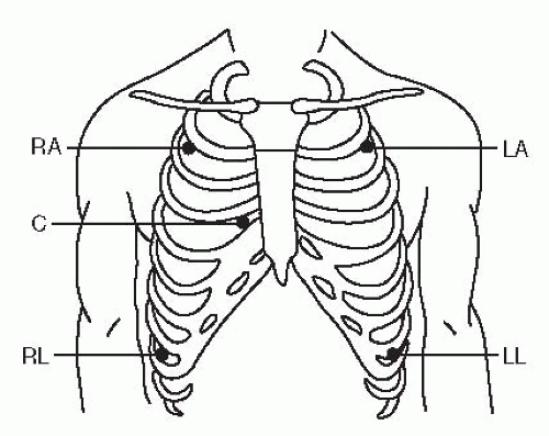
With the five-leadwire system (Figure 4-1), five electrode pads and five leadwires are used. One electrode is placed below the right clavicle (2nd interspace, right midclavicular line), one below the left clavicle (2nd interspace, left midclavicular line), one on the right lower rib cage (8th interspace, right midclavicular line), one on the left lower rib cage (8th interspace, left midclavicular line), and one in a chest lead position (V1 to V6). The six chest lead positions (Figure 4-2) include:
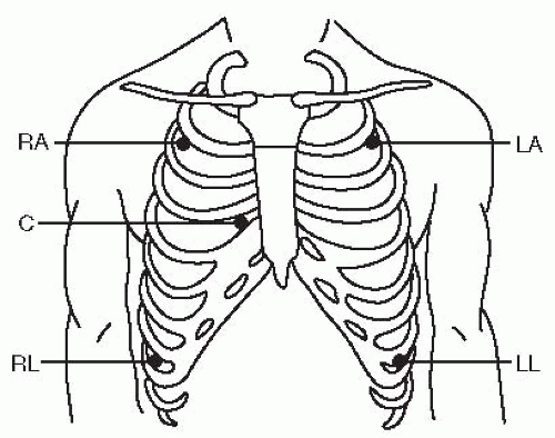 Figure 4-1. Hardwire monitoring — Five leadwire system. This illustration shows you where to place the electrodes and attach leadwires using a five-leadwire system. The leadwires are color-coded as follows: ▪ white — right arm (RA) ▪ black — left arm (LA) ▪ green — right leg (RL) ▪ red — left leg (LL) ▪ brown — chest (C). Leads placed in the arm and leg positions as shown allow you to view leads I, II, III, aVR, aVL, and aVF. To view chest leads V1-V6, the chest lead must be placed in the specific chest lead position desired. In this example, the brown chest lead is in V1 position. |
▪ V1 – 4th intercostal space, right sternal border
▪ V2 – 4th intercostal space, left sternal border
▪ V3 – midway between V2 and V4
▪ V4 – 5th intercostal space, left midclavicular line
▪ V5 – 5th intercostal space, left anterior axillary line
▪ V6 – 5th intercostal space, left midaxillary line
The right arm (RA) lead is attached to the electrode pad below the right clavicle; the left arm (LA) lead to the electrode pad below the left clavicle; the right leg (RL) lead to the electrode pad on the right lower rib cage; the left
leg (LL) lead to the electrode pad on the left lower rib cage; and the chest lead to the electrode pad of the specific chest position desired (V1 through V6).
leg (LL) lead to the electrode pad on the left lower rib cage; and the chest lead to the electrode pad of the specific chest position desired (V1 through V6).
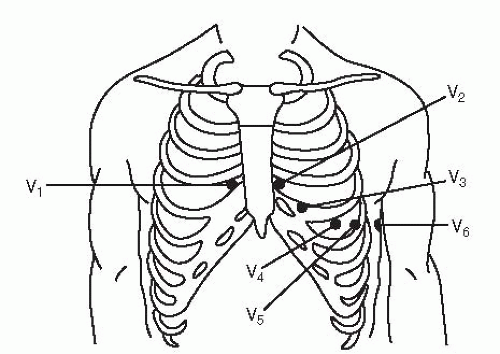 Figure 4-2. Chest lead positions. |
With the five-leadwire system for hardwire monitoring, you can continuously monitor two leads using a lead selector on the monitor. Leads placed in the arm and leg positions allow you to view leads I, II, III, AVR, AVL, and AVF (Figure 4-1). To view chest lead V1 to V6, the chest lead must be placed in the specific chest lead position desired. Generally, a limb lead (usually I, II, or III) and a chest lead (usually V1 or V6) are chosen to be monitored.
With the three-leadwire system (Figure 4-3), three electrode pads and three leadwires are used. One electrode pad is placed below the right clavicle (2nd interspace, right midclavicular line), one below the left clavicle (2nd interspace, left midclavicular line), and one on the left lower rib cage (8th interspace, left midclavicular line). The RA lead is attached to the electrode pad below the right clavicle, the LA lead is attached to the electrode pad below the left clavicle, and the LL lead is attached to the electrode pad on the left lower rib cage. You can monitor either limb leads I, II, or III by turning the lead selector on the monitor. Although you can’t monitor chest leads (V1 to V6) with a three-leadwire system, you can monitor modified chest leads that provide similar information. To monitor any of these leads, reposition the LL lead to the appropriate position for the chest lead you want to monitor, and turn the lead selector on the monitor to lead III. Examples of modified chest lead V1 (MCL1) and modified chest lead V6 (MCL6) are shown in Figure 4-4.
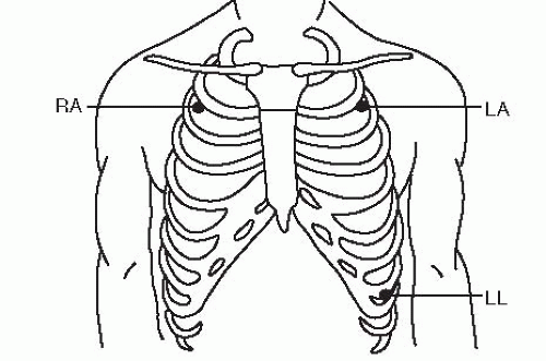 Figure 4-3. Hardwire monitoring — Three-leadwire system. This illustration shows you where to place the electrodes and attach leadwires using a three-leadwire system. The lead wires are color-coded as follows: ▪ white — right arm (RA) ▪ black — left arm (LA) ▪ red — left leg (LL). Leads placed in this position will allow you to monitor leads I, II, or III using the lead selector on the monitor. |
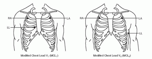 Figure 4-4. Hardwire monitoring — Three-leadwire system: Leads MCL1 and MCL6. Modified chest leads can be monitored with the three-leadwire system by repositioning the left leg (LL) lead to the chest position desired and turning the lead selector on the monitor to lead III. |
 Get Clinical Tree app for offline access 
|


