Fig. 3.1
Diagram of the cardiac conduction system and action potential. Firstly, the sinoatrial (SA) node at the junction between the superior vena cava and the right atrium initiates the electronic pulse in the cardiac conduction system. The penetrating bundle perforates the insulating tissue plane of the atrioventricular (AV) junction to be the only bridge of muscular continuity between the atrial and ventricular myocardium. SA node sinoatrial node, AV node atrioventricular node
3.2.2 Mechanism of Cardiac Arrhythmia
In the tissue level, the pathogenesis of cardiac arrhythmia is based on the triggers and sustainer of arrhythmia (Fig. 3.2).
The arrhythmogenic substrate to trigger or maintain the arrhythmia can be located in the normal cardiovascular structure as well as the injured myocardium.
Of the various cardiac arrhythmias, also atrial fibrillation (AF) can be initiated by the rapid firing of ectopic foci or the reentrant wavelets [1–3].
Depending on the location of arrhythmogenic substrate, the mechanisms of AF are classified into four patterns: pulmonary vein (PV) trigger, reentrant wavelet in the left atrium, non-PV triggers, and ganglionic plexus overactivity.
The common locations of PV triggers and non-PV triggers are located in the posterior wall of the left atrium.
A number of non-PV sites (e.g., the superior vena cava [SVC], coronary sinus [CS], ligament of Marshall, crista terminalis, and posterior wall of left atrium) that share an embryologic relationship to the sinus venosus have been involved as the triggers and sustainer of AF.
Reentrant wavelet in the left atrium can be associated with the atrial remodeling and the injured myocardium and have a potential of reentry induction of AF.
Parasympathetic ganglionic plexuses as the vagus plexuses of the heart are located in the fat pad of superior and inferior cavoatrial junction.
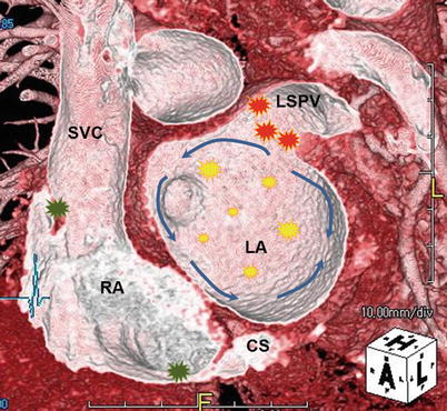
Fig. 3.2
Mechanism of atrial fibrillation. On the left atria and right atria, the four different patterns for atrial fibrillation (AF) consist of the pulmonary vein (PV) triggers, the reentrant wavelets, the non-PV triggers, and the ganglionic plexus overactivity. The posterior wall of the left atrium is considered as the common location of PV triggers (red star) and non-PV triggers (yellow star). Blue arrows demonstrate reentrant wavelets to initiate and sustain the AF. Most of the cardiac ganglionic plexuses (green star) are in the left atrial fat pad near the inferior and superior vena cava. SVC superior vena cava, RA right atrium, CS coronary sinus, LA left atrium, and LSPV left superior pulmonary vein
3.3 Electrophysiologic Intervention and Pre-procedural Cardiac Imaging
3.3.1 Electrophysiologic Intervention
Under fluoroscopic guidance, intracardiac catheters are passed into the right atrium or right ventricle (Fig. 3.3).
Arteriovenous conduction is studied by positioning a separate catheter across the tricuspid annulus and obtaining a His bundle electrogram.
To record activity from the left atrium (LA) and the left ventricle, a catheter is guided into the coronary sinus.
Left-sided procedures in the LA and left ventricle are performed with a transseptal approach or with a retrograde approach from the femoral artery.
In the catheter ablation of AF, the most common catheter technique includes the isolation of PVs using a circumferential extraostial ablation on the atrial side of the PVs (Fig. 3.4).
Catheter ablation can create a linear or box-shaped ablation lesion set around the posterior wall of the left atrium, because the non-PV trigger points are commonly located in the posterior wall of the LA rather than the PV [4].
To achieve the successful management of AF, additional stepwise approach can make multiple linear ablations focusing on the roof of LA, mitral isthmus, coronary sinus, and superior vena cava.
The role of cardiac resynchronization therapy (CRT) has been established in medically refractory, systolic heart failure with abnormal QRS duration and morphology.
The CRT with pacing of the left ventricle is accomplished via the coronary sinus.
In the cardiac venous system, the left marginal vein and posterolateral vein along the lateral border of the left ventricle are considered as the target veins for pacemaker lead placement in CRT.
Pacing in a scarred region may provide inadequate resynchronization, and a posterolateral scar is a strong predictor of nonresponse of CRT.
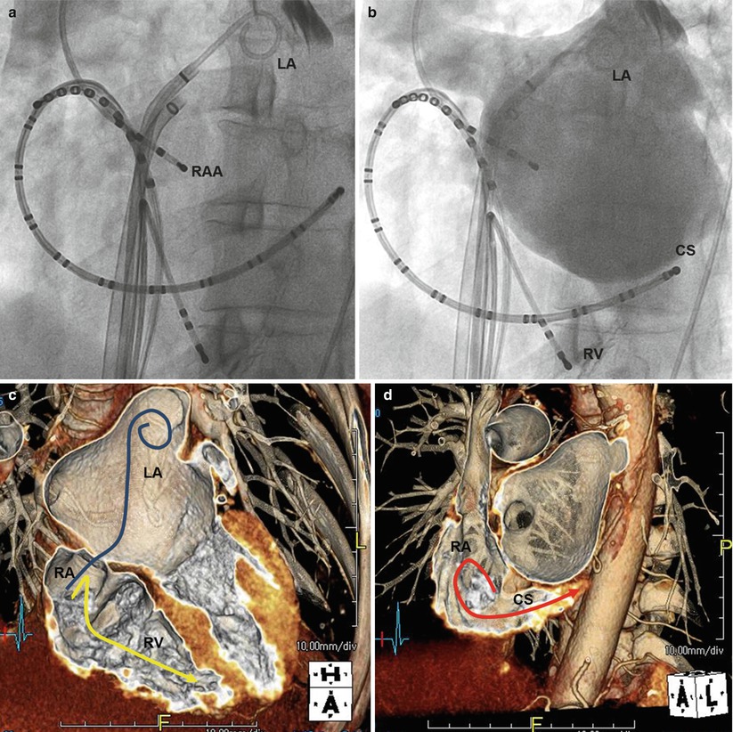
Fig. 3.3
Interventional electrophysiologic approach. For the fluoroscopy, radiographies (a, b) show three intracardiac catheters, which have been introduced via the inferior vena cava into the coronary sinus, the right ventricular apex, and the right atrial appendage. Volume-rendered CT images (c, d) show the routes of intracardiac catheters into CS (red line), RV apex (yellow line), and the transseptal puncture over the oval fossa to perform the left-sided procedure (blue line) in the LA. RA right atrium, RAA right atrial appendage, LA left atrium, CS coronary sinus, RV right ventricle
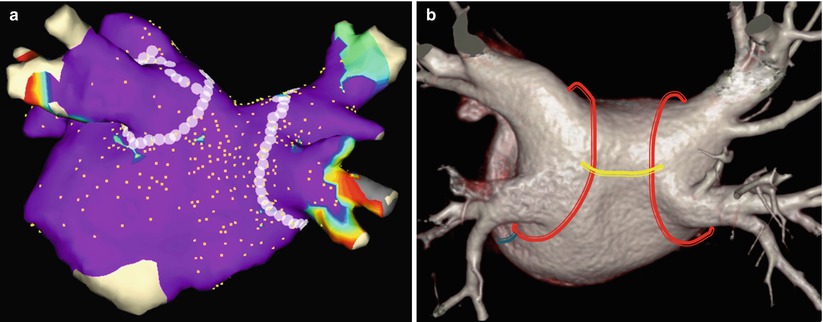
Fig. 3.4
Catheter ablation strategies for atrial fibrillation. Posterior electroanatomic map (a) and volume-rendered CT image (b) of the left atrium and pulmonary vein show the circumferential pulmonary vein ablation. In volume-rendered CT image (b), circumferential ablation line (red) around two pulmonary vein lesions is connected by a roof ablation line (yellow). A mitral isthmus ablation line (blue) is creased between the left inferior pulmonary vein and the lateral mitral annulus
3.3.2 Cardiac Imaging Modality
With introduction of multidetector computed tomography (CT), cardiac CT image can provide excellent temporal and spatial resolutions, which are sufficient for pre-procedural evaluation before the electrophysiologic intervention.
Despite the presence of irregular heartbeat, the retrospective electrocardiography (ECG)-gated CT covering the entire cardiac cycle can provide a better image quality for advanced 3D post-processing and catheter guidance system.
Retrospective ECG-gated cardiac CT image reconstructions can be performed at 10 % increments throughout the cardiac cycle in addition to three fixed temporal delay reconstructions in end systole at 150, 200, and 250 ms.
For the pre-procedural cardiac CT imaging, the bolus injection of contrast media can be followed by the admixing of contrast media and saline (e.g., 30 % contrast media, 70 % saline) at the end of the injection to reduce the streak artifacts and evaluate the right heart (Fig. 3.5).
Cardiac magnetic resonance (MR) imaging has been tried to alternate the CT image. But, one potential limitation of cardiac MR is the contraindication to imaging patients with pacemakers and defibrillator (Fig. 3.6).
The best merit of cardiac MR imaging is to delineate the injured myocardium. When using the late-gadolinium enhancement MR sequence to evaluate the myocardial scar, the prognosis and treatment result after the electrophysiologic intervention can be predicted [5–7].
Time-resolved contrast-enhanced MR angiography of the pulmonary vein can be used to provide a “road map” for catheter ablation of AF [8].
In 2008, the feasibility of a live cardiac MR during the catheter ablation procedure was reported [9]. The potential advantage of such live MR setting is to ascertain the live formation of complete pulmonary vein scar by radiofrequency ablation.
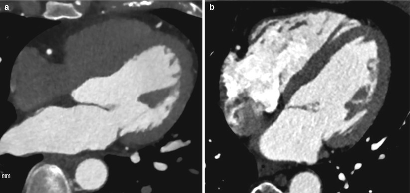
Fig. 3.5
Cardiac CT imaging to evaluate the right heart. When compared to the conventional coronary CT image (a), the cardiac CT image (b) to guide the electrophysiologic intervention was obtained by flushing of admixture with contrast media and saline and can help to delineate the right heart chamber more clearly
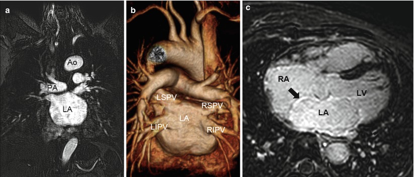
Fig. 3.6
Cardiac MR images to prepare the catheter ablation of atrial fibrillation. In the basis of three-dimensional time-resolved contrast-enhanced MR angiography (a), the volume-rendered MR image (b) provides the virtual appearance of the left atrium and pulmonary vein for the “roadmap” in the catheter ablation. Sequentially, late-gadolinium enhancement MR image (c) shows the myocardial injury of well enhancement (arrow) along the interatrial septum in patients with atrial fibrillation. Ao aorta, PA pulmonary artery, LA left atrium, LSPV left superior pulmonary vein, LIPV left inferior pulmonary vein, RSPV right superior pulmonary vein, RIPV right inferior pulmonary vein, RA right atrium, and LV left ventricle
3.4 Discerning Appearances of Cardiac Structures in the Electrophysiologic Intervention
3.4.1 Right Atrium
The right atrium (RA) as the chamber of the heart that receives systemic venous blood return is located anterior to the LA.
The RA consists of the appendage, the venous part (sinus venarum), and the vestibule.
The anatomic characteristic of RA is the crista terminalis, “C-shaped muscular ridge” separating the smooth-walled sinus venarum from the trabeculated appendage (Fig. 3.7).
The RA includes the important conduction components such as the SA node and AV node.
In the terminal groove corresponding internally to crista terminalis, the SAN is located near the superior cavoatrial junction.
The AV node is located within the boundaries of Koch’s triangle, an important anatomic landmark for electrophysiologic study (Fig. 3.8).
Koch’s triangle is bordered posteriorly by the tendon of Todaro (fibrous extension from the eustachian ridge), anteriorly by the septal leaflet of the tricuspid valve, and inferiorly by the ostium of the coronary sinus.
The central fibrous body at the apex of Koch’s triangle is a landmark of penetrating His bundle in the atrioventricular (AV) junction.
Using the cardiac CT image, Yasushi et al. reported that a large RA volume (≥99 mL) at the end systole of the left ventricle was significantly associated with AF recurrence after catheter ablation [10].
The inferior wall of the RA between the inferior PV and the tricuspid valve is a quadrilateral region as cavotricuspid isthmus (CTI) as the ablation target for isthmus-dependent atrial flutter [11].
In the inferior wall of the RA, obstacles such as large eustachian ridge, aneurysmal pouches, or a concave deformation of CTI may lead to more difficult ablation sessions [12].
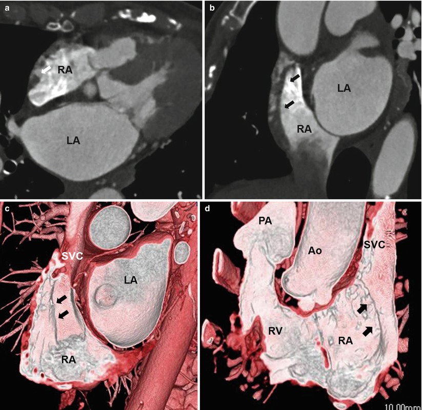
Fig. 3.7
Crista terminalis. Transverse (a), coronal-reformatted (b), and volume-rendered (c, d) CT images show the crista terminalis (arrows) extending from the superior vena cava to the inferior vena cava. Ao aorta, PA pulmonary artery, LA left atrium, SVC superior vena cava, RA right atrium, and RV right ventricle
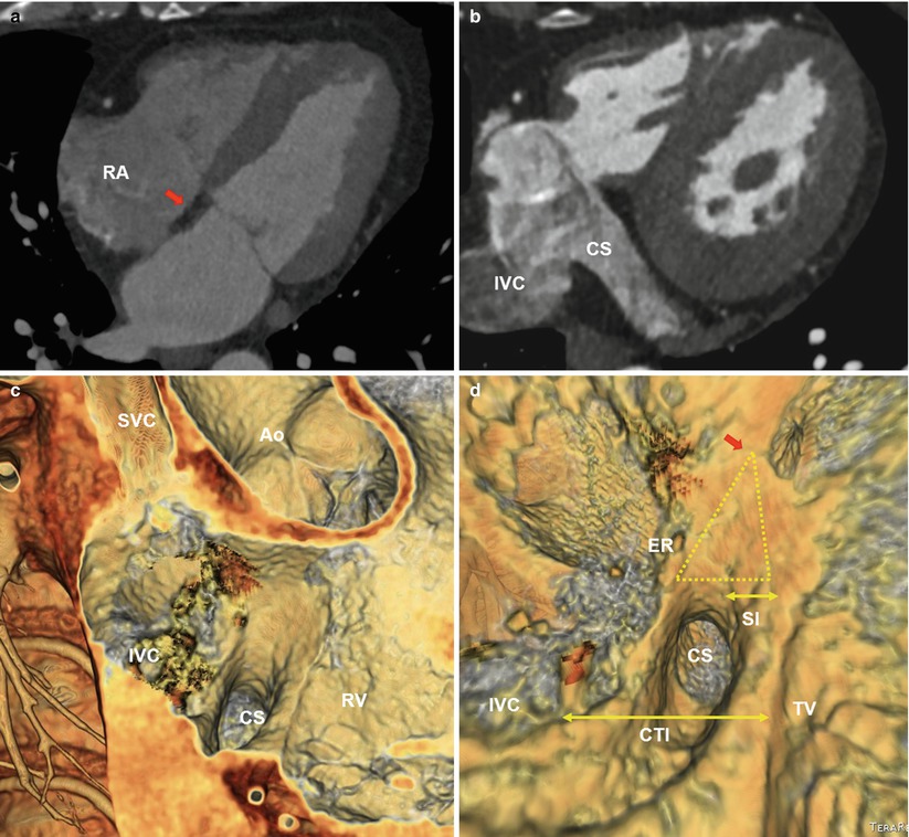
Fig. 3.8
Koch’s triangle, eustachian ridge, and cavotricuspid isthmus. Transverse cardiac CT images (a, b) show the central fibrous body (CFB) (red arrow) and coronary sinus as the borders of the Koch’s triangle. Endocardial view CT images (c, d) of the right atrioventricular (AV) junction shows Koch’s triangle (yellow triangle) and the right atrial isthmus (small double arrows). Koch’s triangle is demarcated by the tendon of Todaro–Eustachian ridge (ER) posteriorly, the septal tricuspid valve anteriorly (yellow arrows), coronary sinus (CS) inferiorly, and central fibrous body (CFB) at the apex (red arrow). The septal isthmus (SI), the area between the CS and septal tricuspid valve, is the target for ablation of AV node reentrant tachycardia. The CTI (large double arrow) is defined as the inferior wall of the right atrium between the inferior vena cava and the tricuspid valve. The CTI is the target of catheter ablation for isthmus-dependent atrial flutter. Ao aorta, RA right atrium, SVC superior vena cava, IVC inferior vena cava, RV right ventricle, SI septal isthmus, and TV tricuspid valve
3.4.2 Cardiac Venous System
The cardiac veins can be grouped into the following categories, according to the region being drained: the coronary sinus (CS) and its tributaries, the anterior cardiac veins, and the Thebesian veins.
The Thebesian veins (venae cordis minimae) are a number of small veins that drain the subendocardium and are continuous with the endothelial lining of the cardiac chambers.
CS is the most constant structure emptying into the LA and can be used as a conduit for the catheter treatment of arrhythmias as well as the left ventricular pacing.
The major tributaries of the CS include the anterior interventricular vein, the great cardiac vein (GCV), the left marginal vein, the posterior vein, and the middle cardiac vein.
Congenital coronary sinus anomalies include diverticulum, stenosis, ectasia, unroofed sinus, ostial atresia, agenesis, and duplication (Fig. 3.9).
In the pathogenesis of AF, the CS enveloped by muscular fibers as the connections to the LA can be considered as the non-PV triggers.
As the minor cardiac vein, the vein of Marshall runs inferiorly along the LA inferior wall to join the CS with muscular connections to the left PVs. So, the ligament or vein of Marshall can be another origin of non-PV trigger for AF (Fig. 3.10).
Also the persistent LSVC draining into the CS can act as the non-PV triggers.
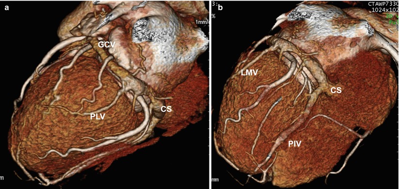
Fig. 3.9
Cardiac venous anatomy. Three-dimensional images (a, b) shows normal cardiac venous anatomy including the coronary sinus. The great cardiac vein (GCV) receives two main branches: the left marginal vein (LMV) in the lateral border of the left ventricle and the posterolateral vein (PLV). CS coronary sinus, PIV posterior interventricular vein
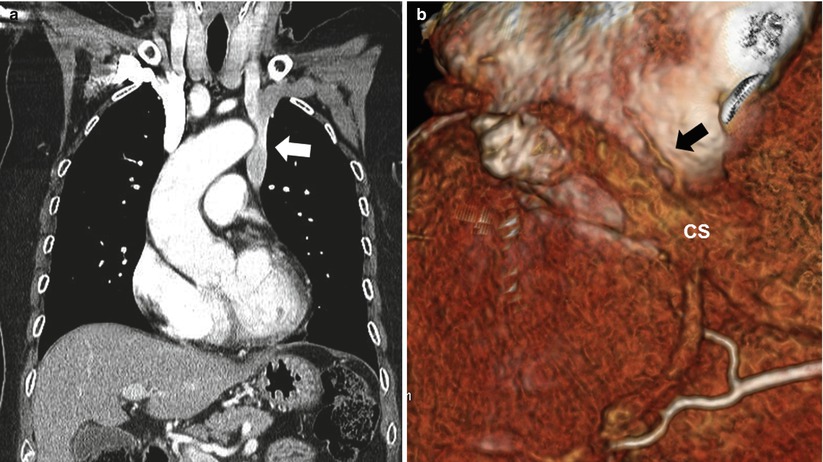
Fig. 3.10
Persistent left SVC and vein of Marshall. Coronal-reformatted CT image (a) shows preferential drainage of blood into the left SVC (arrow) from the left brachiocephalic vein. The 3D CT image of the inferior wall of the heart (b) shows the vein or ligament of Marshall (arrow) as the remnant of the left superior vena cava, which descends between the left atrial appendage and left pulmonary vein to join into the coronary sinus (CS)
3.4.3 Interatrial Septum
The interatrial septum with complex process of several tissue components comprises the foramen ovale (septum primum) which is a flap valve and typically fuses by early adulthood.
The flap of the foramen ovale closes against the atrial septum, with fusion usually occurring within the first 2 years of life. Incomplete fusion results in probe patent defect, or patent foramen ovale (PFO).
The foramen ovale is the only portion of the septum that can be traversed without risk of exiting the heart.
Common anatomic variation of the interatrial septum includes PFO, atrial septal aneurysm, atrial septal defect, and lipomatous hypertrophy of the septum (LHS) (Fig. 3.11).< div class='tao-gold-member'>Only gold members can continue reading. Log In or Register to continue
Stay updated, free articles. Join our Telegram channel

Full access? Get Clinical Tree


