Cardiac catheterization and intervention
Radiation protection in the catheterization laboratory
All practitioners delivering ionizing radiation during medical procedures must attend a radiation protection course (IRMER, Ionising Radiation Medical Exposure Regulations 2000). Furthermore, staff working in the catheterization laboratory should be issued with radiation-monitoring badges, for the body and neck, which should always be worn while in the lab. These badges should be checked monthly to assess doses of radiation received by individual members of staff. No unnecessary staff should be within the catheterization lab during a procedure, and all staff that need to be in the lab should be as far from the tube as practical.
Minimizing patient dose
Minimizing operator dose
The dose for an interventional cardiologist has been calculated as 60 mSv (based upon 150 working days per year and 4 interventions per day). The calculated effective dose if the operator wears the correct lead apron and thyroid collar is less than 5 mSv/year. The maximum allowed dose is 20 mSv/year.
Vascular access: the femoral artery
Procedure for femoral artery access
Sheath removal
(see Vascular access site management, p. 316)
Complications
Vascular access: the radial artery
The radial approach for coronary angiography is now widely accepted. There are several advantages, including a reduction in vascular complications, and the ability to mobilize patients immediately following their procedure. Patient selection for radial access should include palpation of the radial artery to confirm pulsations are present and then an Allen’s test. In the absence of robust supply via the ulnar artery, the radial approach should not be used.
Procedure for radial artery approach
Complications
Radial artery spasm is the commonest complication of radial artery puncture and sheath introduction. There are various techniques to try and prevent radial artery spasm from occurring, these include:
Common radial pitfalls and solutions
Vascular access site management
Femoral sheath removal
Femoral sheaths should only be removed by fully trained members of staff. After diagnostic coronary angiography, when no or little heparin is given, the sheath may be removed immediately. Direct pressure should be applied just proximal to the site of the skin puncture for 5 to 10 minutes. After angioplasty, it is routine to wait for between 4 to 6 hours, an activated clotting time (ACT)<150 s suggests that the effect of systemic heparinization is wearing off, and it is acceptable for the sheath to be removed. Femoral clamps (FemoStop®, RADI Medical Systems) can be used to reduce bleeding complications in patients.
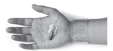
Radial sheath removal
Radial sheaths are removed immediately after both diagnostic angiograms and angioplasty, as the position of the artery renders compression more simple. Compression bands (RadiStop®, RadiMedical Systems USA, TR-Band™, Terumo). See Fig. 6.3.
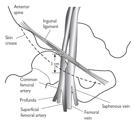
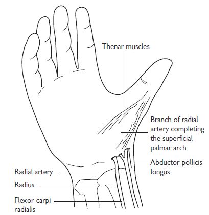
Fig. 6.2 Radial artery anatomy.

Vascular closure devices
Until recently, mechanical compression was the only method for controlling bleeding from vascular access sites in the groin. Larger sheaths and the advent of the more widespread use of glycoprotein (GP) IIb/IIIa inhibitors have increased the risk of bleeding, and made homeostasis more difficult. Recently, various closure devices have been introduced; the aim of these is to increase patient comfort, and reduce puncture-related complications.
Suture-based closure devices
Perclose® (Abbot Vascular, USA): this delivers a suture to the arterial puncture site. The device is sheath-like in nature; needles are positioned above the sheath in the handle, and are deployed by a plunger. A ‘clincher’ that performs a knot-tying function completes a sliding knot.
Collagen-based closure devices
Devices that utilize a bioresorbable collagen plug that is deposited at the site of arteriotomy via a sheath; such devices include the VasoSeal® (Datascope Corp, USA) and Angio-Seal® (St Jude Medical, USA, see Fig. 6.4).
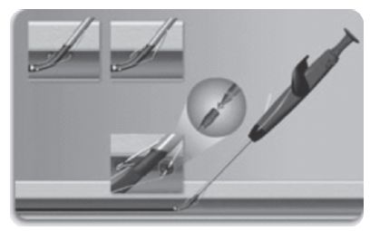
Fig. 6.4 Angioseal™ vascular closure devices.
Other mechanical closure devices
StarClose® features a Nitinol® clip that is designed to promote the primary healing process to achieve a secure closure of femoral artery access sites following diagnostic or interventional vascular procedures. This clip provides 360-degree tissue apposition for rapid healing and haemostasis.
Drug-based closure devices
Clo-Sur® PAD (Medtronic, USA): this device contains a naturally occurring biopolymer polyprolate acetate. This polymer has a coagulant property when brought into contact with heparinized blood. The device is placed over the puncture and the haemostatic sheath is removed. Direct continuous pressure is applied until haemostasis is achieved.
Radial closure device: TR Band™ (see Fig. 6.4)
How to place a TR band
Coronary angiography
Pre-shaped coronary angiographic catheters
The catheters used in diagnostic coronary angiography come in a wide variety of preformed shapes. In the UK, the most commonly used pre-shaped catheters are the Judkins Left 4 and Judkins Right 4 (known as the JL4 and JR4 respectively), used to image the left and right coronary arteries, and the pigtail catheter, used for left ventriculography. The diameter of catheters is measured in French gauge (Fr); catheters between 4Fr (0.053″) and 8 Fr (0.105″) are commonly used.
Commonly used cardiac catheter shapes
See Fig. 6.5.
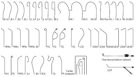
Fig. 6.5 Commonly used cardiac catheter shapes.
Catheter advancement and manifold usage
A ‘J’-tipped 0.035″ guide wire is placed within the flushed catheter, which is then passed into the haemostatic sheath. The guide wire is advanced ahead of the catheter under fluoroscopic guidance, until it reaches the aortic root, just above the aortic valve. The catheter is then advanced to this position and the guide wire is removed. To ensure that no air or clot is within the catheter, a small volume of blood (5 mL) is aspirated from the catheter directly into a syringe and discarded. The catheter is then carefully connected to a two-way manifold, which allows pressure monitoring, saline flushing, and contrast injection through a closed system.
Contrast injection
Great care must be taken at all times to ensure that air is not injected into the coronary arterial tree. The injection syringe should be filled with contrast from the reservoir, and then the syringe held with the plunger elevated so that any air bubbles rise to the top of the syringe. Contrast should then be injected at a continuous rate, aiming to full opacify the coronary vessel of interest. Care should be taken that the pressure trace is normal before injection—damping suggests an ostial stenosis, excessively deep intubation, or selective intubation of a branch.
Coronary angiography/left ventriculography
Left coronary artery
Right coronary artery
Left ventriculography
Interpreting the coronary angiogram
Left coronary artery (LCA) angiographic views (Fig. 6.6)
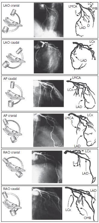
Fig. 6.6 LCA angiographic views. Reproduced with permission from Braunwald E (ed) (2001). Heart Disease: a textbook of cardiovascular medicine. 5th ed. Philadelphia: WB Saunders.
Right coronary artery (RCA) angiographic views (Fig. 6.7)
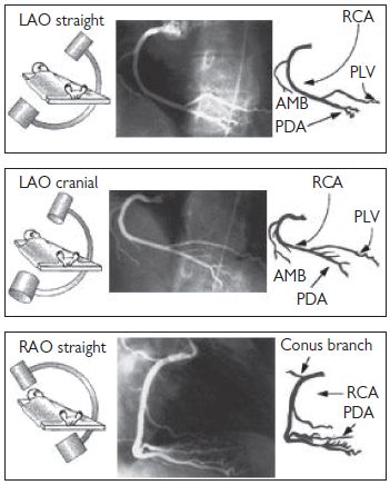
Fig. 6.7 RCA angiographic views. Reproduced with permission from Braunwald E (ed) (2001). Heart Disease: a textbook of cardiovascular medicine. 5th ed. Philadelphia: WB Saunders.
Angiographic study of grafts
It is important to study the surgical record to ascertain how many grafts were placed at the time of the operation. Sometimes, useful information (often from a surgeon’s diagram) can be obtained as to the position in the ascending aorta that the grafts arise from. As a rule, leftwards-facing grafts are best cannulated from the RAO 50 projection, and rightwards-pointing grafts are best cannulated in the LAO 50 projection. It may be necessary to perform an aortogram to visualize the position of grafts. Specialist catheters (e.g. the left coronary bypass catheter or LCB) have been designed to aid cannulation of grafts.
There is usually a predictable anatomy:
Common aortic positions for placement of saphenous vein graft (SVG) (Fig. 6.8)
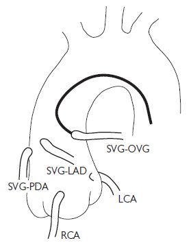
Fig. 6.8 Common aortic positions for placement of SVG. OVG = omniflow vascular graft. Reproduced with permission from Braunwald E (ed) (2001). Heart Disease: a textbook of cardiovascular medicine. 5th ed. Philadelphia: WB Saunders.
Complications of angiography
Peripheral vascular complications
Haematoma
The incidence of haematoma formation is related to the following factors:
Features that suggest a haematoma may require further investigation are an overlying bruit, expansile mass, and a large tense swelling.
Pseudoaneurysm (Fig. 6.9)
A pseudoaneurysm represents a rupture of the femoral arterial wall at the site of puncture, with the formation of a false aneurysm involving the media and adventitia. It is best visualized on ultrasound examination. Small pseudoaneurysms can often be managed by direct compression; however, large pseudoaneurysms may require thrombin injection, or surgical intervention.
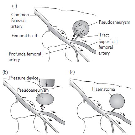
Fig. 6.9 Anatomy of a pseudoaneurysm. (a) Bleeding along a small tract allows blood to collect within the extravascular tissues. Manual compression fails to obliterate the tract (b), and allows the haematoma to persist. Failure of thrombosis of the haematoma produces an extravascular collection with persistent connection and flow from the main artery (c). This can be visualized on ultrasound scan (USS).
Haemorrhage
If prolonged, then direct pressure (either manually or using a clamping device) may be needed. Heparin anticoagulation can be reversed using protamine.
Limb ischaemia
This is rare, and usually occurs in patients with pre-existing limb ischaemia. If limb ischaemia is suspected, then urgent review by the vascular surgical team should be sought.
Contrast reactions
Mild contrast reactions such as rash, urticaria, blurred vision, and rigors are relatively common. These symptoms may settle spontaneously, but are often treated with a combination of IV chlorphenamine 10 mg and IV hydrocortisone 100–200 mg. Anaphylactic reactions are rare; these should be treated with chlorphenamine and hydrocortisone, but also plasma expanders and IM adrenaline.
Vasovagal reactions
These are common both during angiography and at the time of sheath removal, and characterized by hypotension and bradycardia. They are treated with IV atropine and volume expanders.
Arrhythmia
Brief episodes of supraventicular tachycardia (SVT) are common and often transient. During catheter manipulation (especially in the left ventricle (LV)), salvoes of VT are common. Ventricular fibrillation (VF) may occur during coronary artery injection, and should be treated with rapid defibrillation.
Radial arterial complications
One of the main advantages of the radial route is a reduction in complication rates.
Bleeding
This is more easily managed with direct pressure than from the femoral route.
Compartment syndrome
This is a rare, but potentially catastrophic complication.
Pseudoaneurysm
Rare. Manage as per femoral pseudoaneurysm.
Radial artery occlusion
The rate of radial artery occlusion following radial artery cannulation is unclear—but is probably between 1% and 5%. The rate of occlusion is reduced with smaller sheath sizes, hydrophilic sheaths, and heparin administration.
Right-heart catheterization
Indications for right-heart catheterization include:
The acute settings in which right heart catheterization can be helpful (e.g. intensive drug therapy in cardiogenic shock) will not be discussed here.
Access to the right heart is usually achieved via the right femoral vein (RFV). The RFV is located 0.5 cm to 1 cm medial to the femoral arterial pulsation (see Vascular access: the femoral artery, Fig. 6.1, p. 313). An 18-gauge needle, attached to a syringe that is partially filled with saline, can be used to locate the position of the vein, followed by the larger-bore needle. When venous blood is freely aspirated, a 0.035″ guide wire is passed into the vein, using a technique similar to femoral artery cannulation, and a haemostatic sheath introduced.
Right-heart catheterization protocol
Stay updated, free articles. Join our Telegram channel

Full access? Get Clinical Tree


