Cardiac Anatomy and Physiolog Y: Imaging Aspects
Frank E. Rademakers
The technical capabilities of cardiovascular magnetic resonance (CVMR) and computer tomography (CT) and, consequently, the clinical indications in which they can contribute to better patient management, continue to expand. For some indications, they have become the gold standard whereas for others they are the preferred alternative when echo Doppler fails. However, to be able to translate these superior imaging capabilities into improved patient care requires a good understanding of cardiovascular physiology and pathophysiology.
The purpose of this chapter is to reintroduce some of the general concepts of cardiovascular physiology that can be useful in the interpretation of CVMR and CT still images, perfusion and flow curves, and cine loops.
From the early days of Galen (about 200 ad) and through the times of Servetus (1511), Vesalius (1514), Harvey (1578), Frank (1895), Starling (1918), and many others, the anatomy and function of the heart have fascinated scientists all over the world (Fig. 4.1). Even today, not all of the anatomic and functional aspects of the heart are fully understood. The fiber organization in bundles, lamina, and sheets remains a topic of discussion, and the famous Frank-Starling law cannot be fully explained by present knowledge. Experimental techniques using molecular technology are rapidly adding to our understanding of some of the basic mechanisms, but a noninvasive method like CVMR/CT—with the ability to provide a comprehensive evaluation of morphology, regional and global function, flow, and perfusion—is needed to shed new light on the function of the human heart in vivo.
Cardiovascular disease remains the most important killer in the Western world, so a technique that provides comprehensive information noninvasively and repetitively in the aging population is valuable.
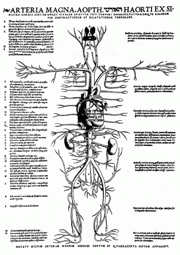 Figure 4.1. Andreas Vesalius (1514-1564) Tabulae Anatomicae: schematic of the circulation. |
Because of the need for a combination of advanced technical skills and a good knowledge of anatomy, physiology, pathophysiology, and patient management, a close cooperation between all disciplines involved will be required for the successful application of these technologies.
FUNCTIONAL ANATOMY
GENERAL ANATOMY
The heart, as a muscle and pump, consists of two serial systems joined in one organ enveloped by the pericardium. It weighs between 250 and 350 g and is located in the mediastinum. It extends obliquely from the second rib to the fifth intercostal space and spans about 13 cm.
The heart rests on the superior surface of the diaphragm and is flanked and partially covered by the lungs. Its broad base is directed toward the right shoulder, and the apex points inferiorly toward the left hip. It has four chambers, two inferiorly located ventricles and two superiorly located atria. The heart is divided longitudinally by the fibrous interatrial and the muscular interventricular septum. The right ventricle is the most anterior part of the heart, and the pulmonary trunk is the most anterior vessel. The left ventricle (LV) defines the inferoposterior part of the heart and the apex.
Several grooves (usually filled with epicardial fat) are visible on the surface of the heart, delineating the different cavities and carrying the blood vessels supplying the myocardium. The atrioventricular groove, or coronary sulcus, encircles the junction between the atria and ventricles and contains the right coronary artery, the circumflex coronary artery, and the coronary sinus. The anterior interventricular groove lies at the anterior junction of right and left ventricles and contains the anterior descending coronary artery and the great cardiac vein. The posterior interventricular sulcus marks the same junction on the inferoposterior surface
of the heart and contains the posterior descending artery, which can originate from the circumflex or right coronary artery, as well as the middle cardiac vein. The small cardiac vein runs along the right inferior margin of the heart and empties in the coronary sinus, just before the latter opens into the right atrium (RA).
of the heart and contains the posterior descending artery, which can originate from the circumflex or right coronary artery, as well as the middle cardiac vein. The small cardiac vein runs along the right inferior margin of the heart and empties in the coronary sinus, just before the latter opens into the right atrium (RA).
DEFINING REGIONS AND SURFACES
Definitions of the several surfaces and regions of the heart differ depending on the imaging technique, so that a great deal of confusion can arise when results from echocardiographic, nuclear, angiographic, CT, or CVMR studies are compared. Part of the confusion derives from the reference point used and part from the changing position of the heart in the thoracic cavity that is associated mainly with aging, but also with disease. At a younger age, the heart is more vertically positioned, with a smaller “diaphragmatic” part and a larger “posterior” part.
With aging and in pulmonary disease, the heart assumes a more horizontal position, and the apex is more laterally located; as a result, the contact area with the diaphragm is larger, and the “posterior” face of the heart is more “inferior.” Clearly, the confusion in nomenclature stems from definitions, which are based on external references, body anatomy, or cardiac anatomy. A good example is the comparison of echo with angiography. Echo adapts the acoustic window to obtain a standard view of the heart and from there defines the different regions; angiography uses a standard external positioning of the X-ray tubes and defines regions from the projection boundaries thus obtained.
CVMR and CT provide an unlimited choice of image and/or reconstruction planes; one can, therefore, choose standardized 2-dimensional (2D) slices of the heart (e.g., twochamber, four-chamber, short axis slices) and use intrinsic cardiac anatomy (insertion of right ventricle, papillary muscles) as the reference for naming the different regions. When standard transversal, sagittal, or frontal views are used, the same problems encountered with angiography arise, and one has to be aware of the impact of differing positions of the heart in the thorax on naming the surfaces and regions.
On the other hand, because of its large field of view, CVMR/CT is extremely well suited to depict the relationship of the heart to the surrounding structures and to define masses (i.e., tumors) extending from the surrounding area into the heart or vice versa.
CIRCULATION
The right side of the heart accepts desaturated blood from the body through the inferior and superior vena cava and from the heart itself through the coronary sinus and pumps it through the pulmonary circulation. The left side of the heart receives oxygenated blood from the four pulmonary veins and pumps it into the aorta, from where it is distributed through the systemic circulation to the entire body.
ATRIA
Blood is continuously received in the thin-walled, muscular atria. During systole, when the atrioventricular valves are closed, the atria have a reservoir function and, during fast-filling and diastasis, they function as conduits. Only during atrial contraction do they have an active, boosting function, optimizing ventricular filling. Because no valves are present at the entrance of the veins into the atria, some retrograde blood flow occurs at the time of atrial contraction.
Only the inflow regions of the atria are smooth; the auricula and the anterior wall are muscular and have muscle bundles called the pectinate muscles. Several other structures can be recognized, mainly in the right atrium (RA). The origin of the inferior vena cava (IVC) is delineated by the eustachian valve, which is intended to direct the blood from the IVC toward the interatrial septum, where it crosses the foramen ovale in the prenatal circulation. After birth (and the subsequent normal closure of the foramen ovale, which remains as a depression on the interatrial septum), this flow deviation persists, often with some acceleration and turbulence. Higher in the atrium, but continuous with the eustachian valve, the Chiari network spans the atrium with small chords that can be mistaken for thrombi or vegetations. On the posterior surface of the atrium, the crista terminalis delineates the smooth inlet portion of the right atrium from the highly trabecular auriculum and can sometimes be very prominent and mistaken for an abnormal structure.
The left atrium (LA) receives the four pulmonary veins and has an appendage with a smaller orifice than the one in the RA. The LA appendage may contain thrombi, as in the case of atrial fibrillation, and can be the origin of thrombotic cerebral or peripheral disease.
CVMR/CT can accurately identify the veins emptying in the atria and abnormal pulmonary right venous return to the RA or to the superior vena cava. Stenosis of the pulmonary veins (after ablation for atrial fibrillation) is common and can be quantified, both morphologically and by flow measurements. Flow in the pulmonary veins, used to analyze diastolic function, can be easily obtained, but optimal temporal resolution is required. Abnormal structures or masses seen or suspected on echocardiography can be identified as normal anatomic variants or true thrombi or tumors.
VALVES
During diastole, blood flows from the atria into the ventricles through the mitral and tricuspid valves: The mitral valve, resembling a bishop’s miter, has a larger anterior and smaller posterior leaflet; each leaflet is a flexible, thin sheath of connective tissue that is firmly attached to the mitral valve annulus. This annulus has the shape of a horseshoe, is flexible, does not lie in one plane, and changes shape during the cardiac cycle. On the right side, the tricuspid valve has three leaflets (anterior, posterior, and septal) that differ in size and shape; therefore, this valve is difficult to evaluate morphologically because it can never be captured in one plane. The mitral and tricuspid valves are suspended in the ventricle by the chordae tendineae. These are thin, tendinous structures, connecting the free edges but also some neighboring parts of the valves to the papillary muscles, which are elongated protrusions of the muscular wall of the ventricles. Contraction of the papillary muscles during systole prevents the atrioventricular valves from prolapsing into the atria as pressure rises in the ventricles.
During systole, blood is expelled from the ventricles through the aortic and pulmonary semilunar valves into the aorta and pulmonary artery, respectively. Both the aortic valve and the pulmonary valve are tricuspid, consisting of three pocket-like cusps that are freely suspended in the valve ring.
With regular CVMR, it is difficult to image the thin, fast-moving valve structures, but CT and newer MR techniques, also involving valve tracking, provide an accurate visualization of valve leaflets and openings and permit the direct quantification of a stenotic valve area. However, structures with fast, irregular, or erratic movements, such as endocarditis lesions, can be missed by the average CVMR/CT images.
VENTRICLES
The major difference between the left and right sides of the heart is the difference in load level: The pulmonary circulation is a short, low-pressure system that normally works at a peak of 25 mm Hg whereas the left side of the heart operates at a level of up to 125 mm Hg and drives a longer circuit. This difference has major structural consequences; the wall of the right side of the heart is thinner than that of the left side (2 to 3 mm vs. 9 mm). The purpose of this difference is to normalize wall tension and the tension on the myocardial fibers in the wall (Fig. 4.2).
Fiber tension is difficult to measure or calculate, but it is roughly directly proportional to the pressure in the cavity and the diameter of the cavity and inversely proportional to the thickness of the wall. Other factors, such as the shape of the ventricle and the curvature, also play a role: The more curved, the lower the tension; the flatter the surface, the higher the tension.
A major consequence of the structural difference between the ventricles is the way in which they eject blood. The left ventricle must overcome a larger afterload and the pressure in the cavity must increase to aortic pressure before ejection can start; the former is accomplished mainly by the contraction of fibers running circumferentially (in the mid portion of the wall) and the latter by contraction of more obliquely oriented fibers, which leads to thickening, longitudinal shortening and torsion, and inward motion of the endocardium and ejection. On the right side, the pressure that must be overcome is lower; therefore, ejection starts earlier (the pulmonary valve opens before the aortic valve) and is mainly accomplished by segmental shortening (mostly in the long axis) of the crescent-shaped ventricle rather than by wall thickening. Because the resistance to ejection is lower, the contraction continues for a longer time, and the pulmonary valve closes after the aortic valve.
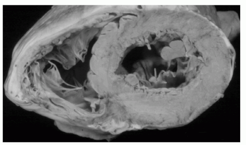 Figure 4.2. Transverse section through the left and right ventricles. |
CVMR/CT can image both ventricles in detail, including the marked intraventricular trabeculation. Because the entire ventricle can be imaged or reconstructed threedimensionally from a stack of short-axis slices, ventricular mass and volume can be derived from the epicardial and endocardial contours. For mass calculations, the trabeculation and papillary muscles are included in the myocardial volume; for functional measurements (wall thickening), they are excluded. Volume and mass measurements are accurate and reproducible and can be used for the follow-up of individual patients. When both end-diastolic and end-systolic images are acquired, wall thickening, stroke volume, cardiac output, and ejection fraction can be calculated. Some difficulties arise at the ventricular apex and base as a result of the tapering of the wall and the erroneous inclusion of some atrial volume secondary to long-axis shortening during ejection; this can be avoided by combining short- with long-axis images and full 3-dimensional reconstruction.
MYOFIBER STRUCTURE
As alluded to earlier, the myofiber structure in the wall of the ventricles is intricate. Although some layers can be recognized in the right ventricle, they are more prominent in the left ventricle. The mid layer is mostly circumferential (circular in short-axis views) whereas the more epicardial and endocardial layers are obliquely oriented, but in an opposite sense: When the ventricle is viewed with the base at the top, the epicardial fibers run from base left to apex right, the endocardial fibers in just the opposite direction and, at the cavity surface, several bundles run completely along the long axis of the ventricle (Fig. 4.3).
The consequence of this changing fiber orientation is that fibers at the epicardium and endocardium are at nearly right angles to each other and will show an interaction or tethering; also, when the oblique fibers contract, the ventricle exhibits a twisting motion or torsion which contributes to the efficiency of ejection. A physical effect of LV torsion is elevation and motion of the apex toward the chest wall, which can be felt as the apical impulse or apex beat; finally, long-axis shortening during systole, produced by oblique and longitudinal fibers, causes the base to move toward the apex, which is nearly stationary because of the fixation of the pericardium to the diaphragm (this fixation is partially lost after the pericardium has been opened, i.e., after cardiac surgery). As a result, when a short-axis slice of the left ventricle is imaged near the base, different parts of myocardium are visualized at end-diastole versus end-systole so that erroneous calculations of segmental shortening and thickening of the wall are possible.
Although MR diffusion imaging can identify local fiber orientation, this is difficult in the in vivo situation because of the concomitant overall motion of the heart. On normal CVMR/CT images, the ventricular wall is seen as a solid,
homogeneous structure. To visualize the different components of myocardial deformation which ensue from the variable fiber orientation (i.e., circumferential, radial, and longitudinal deformation as well as shearing or twisting), a marking or tagging technique must be used. Speckle tracking techniques, as developed for echocardiography, can be used to automatically obtain (regional) deformation.
homogeneous structure. To visualize the different components of myocardial deformation which ensue from the variable fiber orientation (i.e., circumferential, radial, and longitudinal deformation as well as shearing or twisting), a marking or tagging technique must be used. Speckle tracking techniques, as developed for echocardiography, can be used to automatically obtain (regional) deformation.
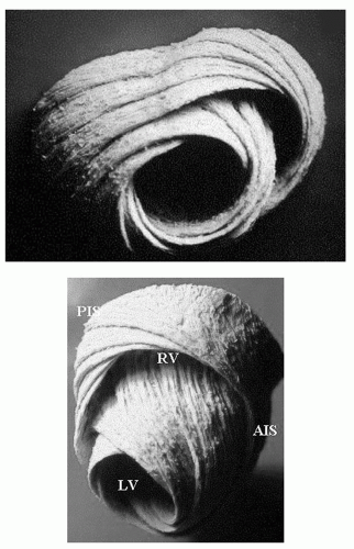 Figure 4.3. Dissection of myofiber layers (Torrent-Guasp). AIS, anterior insertion septum; LV, left ventricle; PIS, posterior insertion septum; RV, right ventricle. |
COLLAGEN MATRIX
The myocardium also has a “scaffold” structure, the fibrous skeleton, consisting of a network of collagen and elastin fibers. This fibrous skeleton supports the myofibers and transmits force throughout the myocardium. Some regions are thicker, that is, at the valvular rings and where the myocardium attaches to the great vessels. Because the fibrous skeleton is not electrically excitable, the ring plane, joining the atrioventricular valves, provides a barrier to electrical conduction, which can be passed only at the atrioventricular node.
PERICARDIUM
The pericardium is a thin, fibrous structure that surrounds the entire heart, except at the entry and exit of the great vessels. It consists of two layers, one adhering to the outer surface of the heart, and another in contact with lungs and other surrounding tissues. The former, the visceral serous layer, is an integral part of the heart wall. The latter consists of a fibrous part and the parietal serous layer. The fibrous part is made of tough, dense connective tissue and anchors the heart to surrounding structures, that is, the diaphragm and the great vessels. Although the pericardium is stretchable, it resists large, sudden increases in cardiac volume; when the volume increase is slow, the pericardium will grow to accommodate the enlarged content.
The parietal serous layer lines the internal surface of the fibrous pericardium and is continuous with the visceral layer as it folds over where the pericardium is attached to the great vessels. The two serous layers are separated by a small amount of lubricating fluid, which accommodates the twisting and shortening movements of the heart during contraction and relaxation. Epicardial and pericardial fat are present in differing amounts, depending on an individual’s constitution. It is found mostly in the atrioventricular and interventricular grooves, containing the epicardial vessels.
Increased amounts of epicardial fat are often mistaken for a pericardial effusion on echocardiography, which is readily recognized on CVMR/CT. Pericardial thickening (>4 mm) can cause constrictive pericarditis, a clinical entity difficult to diagnose. CVMR/CT can easily measure this pericardial thickness; this needs to be done at various locations because thickening and constriction can be confined to one ventricle; on the other, a normal pericardial thickness does not exclude constriction because a thin pericardium can also be excessively stiff. Pericardial calcifications are readily seen on CT.
INTERVENTRICULAR DEPENDENCE
Because of the presence of the constraining pericardium and the fact that they share the interventricular and interatrial septum, the right and left sides of the heart show a great deal of interdependence not only in pathologic circumstances but also in cases of (sudden) ventricular enlargement and in healthy persons. The lower pressure and thinner wall of the right side of the heart make it more vulnerable to compressive forces, but the interdependence between the ventricles works both ways. When filling increases on the right side, as during inspiration, less filling occurs on the left side; in addition, pooling of blood in the pulmonary circulation decreases filling pressures on the left side of the heart. The reverse occurs during expiration, further augmented by the increase in intrathoracic pressure, increasing LV afterload. Interdependence is increased when ventricular volumes are increased (dilated cardiomyopathies) or when the pericardium is more resistant to stretch (stiffer pericardium of constrictive pericarditis or increased intrapericardial pressure of pericardial effusion and tamponade). Pressures in the cavity should always be referred to the pressure in the pericardium which, in normal circumstances, is about the same as pleural pressure (0 to 2 mm Hg) and becomes negative during inspiration. In pathologic conditions, however, intracavitary pressure can be significantly increased by elevated intrapericardial pressure or effective
pericardial resistance. Because this extra pressure is “felt” inside the heart only and not in the supplying veins, there is a resistance to filling; also, during some phases of the cardiac cycle when the pressure drops in the atria and in the (right) ventricle, pericardial pressure can become higher than intracavitary pressure, so that collapse of the cavity ensues.
pericardial resistance. Because this extra pressure is “felt” inside the heart only and not in the supplying veins, there is a resistance to filling; also, during some phases of the cardiac cycle when the pressure drops in the atria and in the (right) ventricle, pericardial pressure can become higher than intracavitary pressure, so that collapse of the cavity ensues.
Another example of the major impact of the pericardium on interventricular dependence is the change in regional motion that occurs after cardiac surgery in which the pericardium was opened. The motion of the interventricular septum can be changed for months afterward, although thickening and intrinsic contractility are unhampered. This is a consequence of the changed interaction between the left and right ventricles after removal of the constraints of an otherwise normal pericardium, whereby the left ventricle shows a more eccentric contraction, and the interventricular septum is nearly immobile in an external reference system. If one were to reposition the images to fix the center of the left ventricle on the screen, contraction would look more normal, but the right ventricle would tend to move outward.
The abnormal motion of the pericardium with respiration, which is a discerning sign in the differential diagnosis between restrictive cardiomyopathy and constrictive pericarditis, can be well observed and quantified with CVMR. The newer, fast imaging techniques allow the identification of the typical morphologic and flow (velocity encoding) changes with the different phases of the respiration. The specific causes of pericardial constriction, such as pericardial thickening, accumulation of fluid, blood, tumor material, or thrombi in the pericardium, can be identified.
ENDOCARDIUM
The endocardium covers the entire inner surface of the heart and valves and has a large surface area because of the extensive trabeculation in both ventricles. Only the subaortic septal region of the LV is completely smooth. The function of the endocardium is still under investigation, but alterations mainly to the relaxation phase have been shown. The endocardium also covers the valves and is continuous with the endothelial lining of the blood vessels as they enter or leave the heart.
Thickening of the endocardium, as in endomyocardial fibrosis, can be well visualized.
CONDUCTION SYSTEM
The conduction system of the heart consists of specialized, spontaneously active cells and a conduction system. The trigger cells are concentrated in specific areas (the sinoatrial node and the atrioventricular node), but impulses can originate all along the conduction system; the intrinsic frequency of these cells, however, decreases from the sinoatrial node to the atrioventricular (AV) node to the His bundle and further in the subendocardial Purkinje system. In normal circumstances, the sinoatrial node is the driving pacemaker of the heart at an average pace of 60 to 70 beats per minute. This cardiac frequency is the result of a balance between parasympathetic and orthosympathetic tone which, at rest, is shifted toward parasympathetic (the intrinsic rate of the sinoatrial node is about 100 beats per minute).
Stay updated, free articles. Join our Telegram channel

Full access? Get Clinical Tree


