Blood Pumps, Circuitry, and Cannulation Techniques in Cardiopulmonary Bypass


Blood Pumps, Circuitry, and Cannulation Techniques in Cardiopulmonary Bypass


Eugene A. Hessel II

Kenneth G. Shann


GENERAL SURVEY OF THE CIRCUIT

The primary function of cardiopulmonary bypass (CPB) is to divert blood away from the heart and lungs and return it to the systemic arterial system, thereby allowing cardiac surgery. Therefore, it must replace the function of both the lungs (gas exchange) and the heart (provide circulation of blood). Typically, blood is drained by gravity (or with some vacuum assistance) through the cannulas in the superior vena cava (SVC) and inferior vena cava (IVC) or IVC and right atrium (RA) (cavo-atrial position) into the heart-lung machine, where it is pumped (with a roller or centrifugal pump) through the artificial membrane-type lung (“oxygenator”) back into the systemic vasculature through an arterial cannula placed in the ascending aorta. (See simplified schematic drawing of basic extracorporeal circuit [ECC] in Fig. 2.1.) A more detailed depiction of the ECC is provided in Figure 2.2.

Because of the need to offset cooling during the extracorporeal passage of blood and the frequent need to intentionally cool and then rewarm the patient, a heat exchanger is included as part of the oxygenator, either before or contiguous with the gas exchange unit.

Peripheral cannulation, using the femoral or other veins and arteries, is occasionally used electively for cardiac surgery when central cannulation is not technically possible. Examples of such situations include initiating bypass before opening the chest, emergent situations, for aortic surgery, for minimal access surgery, and for extracorporeal membrane oxygenation. Left heart bypass or proximal aorta bypass (with “venous cannulation” of the left atrium, left ventricle, or proximal aorta) and distal infusion into the distal aorta or femoral artery, incorporating only an extracorporeal pump, is sometimes used for aortic surgery.

Besides the major venous and arterial connections and the oxygenator, heat exchanger, and pump, there are many other components to the heart-lung machine (Fig. 2.2). An adjustable clamp or remote venous line occluder regulates the main venous drainage line, and a separate tubing clamp is used on the systemic arterial inflow line whenever the patient is not on CPB to prevent backflow out of the arterial cannula, particularly when a centrifugal pump is used. The venous reservoir serves as a buffer for fluctuations in venous drainage and is a source of fluid for rapid transfusion. It is usually positioned proximal to a membrane oxygenator, that is, before the pump but physically attached to the membrane oxygenator housing. Fluids (e.g., blood and crystalloid solutions) and drugs may be added to this reservoir. Several suction devices and systems, usually using one or more of the roller pumps, are used to aspirate blood and gas from the open-heart chambers (hence the term “cardiotomy suction”), pericardium and surgical field, aortic root (during aortic cross-clamping as a left ventricular vent and after unclamping, as an air vent), and left ventricular vent. This blood is then passed into the cardiotomy reservoir, which may be incorporated in the housing of an open (hard-shell) venous reservoir or may first flow into a separate free-standing cardiotomy reservoir before emptying into a separate venous reservoir.

A cardioplegia delivery and/or coronary perfusion system is another component that typically uses one of the roller pumps for administering blood or crystalloid cardioplegia solution into the coronary arteries, aortic root, or coronary sinus. This circuit usually includes a separate heat exchanger and may include a reservoir and sometimes a recirculation line from the surgical field, which is used when cardioplegic solution is not being administered into the heart, although a single-pass delivery system is more commonly used. Often, arterial blood is simultaneously mixed with crystalloid-based cardioplegia solution (often in a 4:1 blood-to-crystalloid ratio) to produce blood cardioplegia.

A source of oxygen, air, and sometimes carbon dioxide, with appropriate flow meters and blenders, supplies ventilating gas to the oxygenator, usually through an in-line anesthetic vaporizer. Although hot and cold water are at times supplied from wall outlets to a mixing valve for adjusting water temperature in the heat exchangers, most commonly a dedicated stand-alone water cooler and heater is used for this purpose. A number of filters (macro or micro) are often included at various sites in the CPB circuit (e.g., cardiotomy reservoir, venous reservoir, oxygenator, arterial line, and cardioplegia system). Also included are sampling ports (pre- and postoxygenator), pressure-monitoring sites such as the cardioplegia-coronary
perfusion delivery line and the arterial line (after the systemic pump but before the arterial filter), and arterial and venous inline blood-gas monitors. Temperature-monitoring sites, such as water inflow and outflow for major heat exchangers, venous and arterial blood, cardioplegia solution, and water bath, are also present. A hemoconcentrator is sometimes attached between the systemic flow line, or some other source of blood under pressure, and the venous or cardiotomy reservoir.


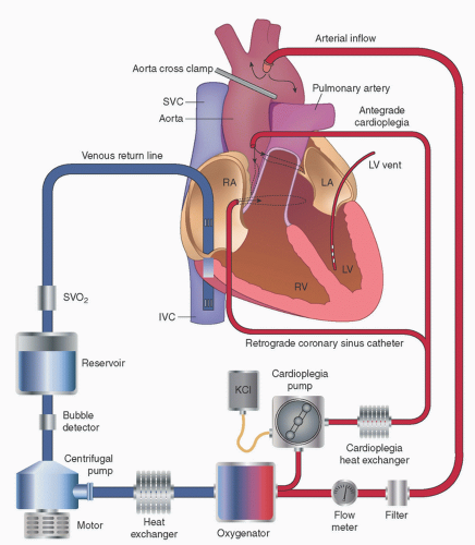
FIGURE 2.1. Simplified extracorporeal circuit diagram. Blood flows by gravity from right atrium and IVC though a cavo-atrial cannula into a venous reservoir. It is then pumped (in this schematic utilizing a centrifugal pump) through a heat exchanger and oxygenator (which are usually integrated as a single membrane oxygenator/heat exchanger) and then through an arterial-line microfilter and is returned to the systemic arterial system (typically the ascending aorta). Also shown are an in-line monitor of venous oxygen saturation, a bubble detector, an arterial-line flow meter, and a cardioplegia delivery system which adds a crystalloid potassium-containing fluid to a source of oxygenated blood, which is then pumped through a separate heat exchanger either into the aortic root (antegrade cardioplegia) or coronary sinus (retrograde cardioplegia). (Redrawn from Miller RD, Pardo MC, eds. Basics of anesthesia. 6th ed. Philadelphia, PA: Elsevier, 2011; used with permission.)

Whenever a centrifugal pump is used, a flowmeter must be included in the systemic outflow line, and a system to prevent retrograde flow (e.g., one-way valve or electronic clamp). Various safety devices and monitors, besides those already mentioned, are frequently incorporated into the CPB circuit. These include pressure monitoring of the systemic arterial and cardioplegia delivery lines, a bubble trap on the arterial line, often incorporating a microfilter and a purge line that includes a one-way
valve that drains back to the venous or cardiotomy reservoir, a bypass line that goes around the arterial filter in case the latter becomes obstructed, an air bubble detector on the systemic arterial inflow line, and a low-level detector and alarm on the venous reservoir.


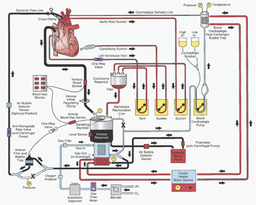
FIGURE 2.2. Detailed schematic diagram of the arrangement of a typical cardiopulmonary bypass circuit using a membrane oxygenator with integral hardshell venous reservoir (lower center) and systemic heat exchanger and external cardiotomy reservoir. Venous cannulation is by a cavo-atrial cannula and arterial cannulation is in the ascending aorta. Some circuits do not incorporate a membrane recirculation line; in these cases the cardioplegia blood source is a separate outlet connector built into the oxygenator near the arterial outlet. The systemic blood pump may be either a roller or centrifugal type. The cardioplegia delivery system (right) is a one-pass combination blood/crystalloid type. The cooler-heater water source may be operated to supply water to both the oxygenator heat exchanger and cardioplegia delivery system. The air bubble detector sensor may be placed on the line between the venous reservoir and systemic pump, between the pump and membrane oxygenator inlet, or between the oxygenator outlet and arterial filter (neither shown), or on the line after the arterial filter (optional position on drawing). One-way valves prevent retrograde flow (some circuits with a centrifugal pump also incorporate a one-way valve after the pump and within the systemic flow line). Other safety devices include an oxygen analyzer placed between the anesthetic vaporizer (if used) and the oxygenator gas inlet and a reservoir level sensor attached to the housing of the hard-shell venous reservoir (on the left). Arrows, directions of flow; X, placement of tubing clamps; P and T (within circles), pressure and temperature sensors, respectively. Hemoconcentrator and Venous cannula (described in text) not shown.

The interested reader may find several other chapters and reviews on heart-lung machines (1,2,3,4,5,6) as well as the recent AmSECT Standards and Guidelines for Perfusion Practice (7) informative.


CANNULATION TO THE PATIENT


Venous Cannulation and Drainage


Principles of Venous Drainage

Venous drainage, often referred to as “venous return,” has traditionally been accomplished by gravity siphonage. However, recently there has been a renewed interest in applying suction to the venous lines, a technique that had been discarded early in the practice of CPB. Siphonage places two constraints on
successful venous drainage. First, the venous reservoir must be below the level of the patient, and second, the lines must be full of blood (or fluid) or else an air lock will occur and disrupt the siphon effect. The amount of venous drainage is determined by the pressure in the central veins (patient’s blood volume), the difference in height between the patient and the top of the blood level in the venous reservoir (negative pressure exerted by gravity equals this height differential in centimeters of water), and the resistance in the venous cannulas, venous line and connectors, and venous clamp, if one is in use.

During CPB, the central venous pressure is influenced by intravascular volume and venous compliance, which is influenced by medications, sympathetic tone, and anesthesia. Excessive drainage (i.e., drainage faster than the speed at which blood is returning to the central veins, which may be caused by an excessive negative pressure caused by gravity or suction) may cause the compliant vein walls to collapse around the ends of the venous cannulas (manifested by line “chattering” or “fluttering” in the venous lines) and intermittent reduction of venous drainage. This may be ameliorated by partially occluding the clamp on the venous line, which may, paradoxically, improve venous drainage, or by increasing the systemic blood volume or administering a vasoconstrictive drug. Obviously, the amount of blood returning to the great veins from the body ultimately limits venous return to the oxygenator.


Types and Sizes of Cannulas

Venous cannulas are either single-stage or “two-stage” (“cavo-atrial”) (Figs. 2.3 and 2.4). The latter has a wider portion with holes in the section designed to be situated in the right atrium and a narrower tip designed to rest in the IVC. Cannulas are usually made of a flexible plastic; most are wire-reinforced to prevent kinking. They may be straight or right-angled. Some of the tips of the right-angled venous cannulas are fabricated out of thin hard plastic or metal for optimal inner diameter (ID) to outer diameter (OD) ratio. The venous cannulas are typically the narrowest component of the CPB venous system and are therefore a limiting factor for venous drainage. Knowing the flow characteristics of the particular cannula, which should be provided by the manufacturer or established by bench-top testing, and the required flow (approximately one-third of total flow from SVC and twothirds of total flow from IVC), one can select the appropriate
venous cannula for a patient. For example, a 1.8 m2 body surface area (BSA) patient (total estimated flow, 5.4 L/min; SVC, 1.8 L/min; IVC, 3.6 L/min) at a siphon (gravity) gradient of 40 cmH2O would require at least a 30 French (F) SVC, a 34F IVC, or a single 38F single-stage catheter (8,9). The sizes of two-stage right atrial catheters, based on the BSA of the patient and maximal achievable flow rates, recommended by Shann and Melnitchouk (10) are listed in Table 2.1. Delius et al. (11) offered a method for describing the performance of cannulas used in extracorporeal circulation, called the M number. They reported the M numbers of several different cannulas and provided a nomogram for determining the “M number” and for predicting the pressure gradient across any cannula at any flow based on this number.


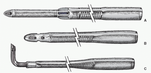
FIGURE 2.3. Drawings of conventional venous cannulas. A: Standard, tapered, two-stage cavo-atrial cannula for insertion into the right atrium (RA) and inferior vena cava (IVC). B: Wire-reinforced cannula for atrial or caval cannulation. C: Cannula with right-angled tip (usually made of metal or hard plastic because the thin wall optimizes the ratio of internal to external diameters). This type of cannula is often used for congenital or pediatric cases and may be inserted directly into the vena cava near its junction with the RA.


FIGURE 2.4. Other venous cannulas. (Kaplan JA, Reich DL, Savino JS, et al. Kaplan’s cardiac anesthesia. 6th ed. Philadelphia, PA: Elsevier, 2011, used with permission.)


TABLE 2.1. Right atrial two-stage cannula, estimated flow rates


BSA (m2)


Size (F)


Max flow (L/min)


Model


Manufacturer


≤1.8


29/37


4.5


Thin-Flex


Edwards Life Science


>1.8 to <2.5


32/40


6.0


MC2


Medtronic


≥2.5


36/46


8.0


MC2


Medtronic


Source: Modified from Table 2-5 of Shann K, Melnitchouk S. Advances in perfusion techniques: minimally invasive procedures. Semin Cardiothorac Vasc Anesth 2014;18(2):146-142.


Connection to the Patient (Sites for Venous Cannulation)

Usually, the venous connection for CPB is accomplished by inserting cannulas into the RA. Three basic approaches are used (Table 2.2 and Fig. 2.5): bicaval, in which separate cannulas are inserted into the SVC and IVC; single atrial; and cavo-atrial (i.e., the “two-stage” approach). The latter has a wider proximal section with holes that lie within the RA and a narrower extension with end and side holes that extends into the IVC. When bicaval cannulas are used, tapes are frequently placed around the cavae and passed through small tubes so that they may be cinched down as tourniquets or snares around the cannula. This forces all the venous return of the patient to pass to the extracorporeal circuit (ECC), preventing any systemic venous blood from getting into the right heart and any air (if the right heart is opened) from getting into the venous lines. This is sometimes referred to as “caval occlusion,” or total CPB.

Other ways of accomplishing this include the use of elastic tapes placed around the cavae and held together with vascular clips and the use of specially designed external clamps that go around the cavae and their contained cannulas. Cuffed venous cannulas may be used, either specially manufactured for this purpose (e.g., model 191037, Medtronic DLP, Inc., Grand Rapids, MI) or cuffed endotracheal tubes. The latter may be helpful in emergency cases and when dissection around the vena cava to place tapes could be particularly difficult or dangerous. When there is a hole in the atrium and it is not possible (or there is not enough time) to insert a purse-string suture, or the suture breaks, a cuffed endotracheal tube may also be used for venous drainage. After insertion, the cuff is inflated and gentle traction tamponades the hole in the atrium so that adequate venous drainage may be provided.

Arom et al. (12) and Bennett et al. (13) compared the efficiency of the various approaches for venous drainage (Table 2.2). Bicaval cannulation with caval occlusion is required any time the right heart is entered. This approach may provide the best caval decompression if properly positioned. However, caval cannulas cause greater interference with venous flow (and hence cardiac output) when not on CPB (i.e., after cannulation but before going on bypass and after bypass but before decannulation). When the caval tapes are tightened, no provision for decompression of the right heart (atrium and ventricle) is provided. If the right ventricle is not able to eject, then the coronary sinus blood returning to the RA must be removed by opening or venting the right heart or releasing the caval tourniquets. This would be aggravated by the presence of a left SVC (LSVC) (see below). When the aorta is cross-clamped, coronary sinus flow is greatly reduced. However, the problem of right heart decompression recurs whenever antegrade cardioplegia or direct coronary perfusion is administered.

Bicaval cannulation without caval tourniquets is often preferred for mitral valve surgery, because the retraction that is necessary often distorts the cavo-atrial junctions and interferes with venous drainage if only a single atrial cannula is used. Right heart decompression is much better without caval tourniquets than when caval tourniquets are used, but may not be as good as with atrial cannulation.

Single atrial cannulation has the advantage of being simpler, faster, and less traumatic, with one less incision, and provides fairly good drainage of both the cavae and the right heart. It interferes least with caval return when off bypass. However, the quality of its drainage of the cavae and right heart is very sensitive to positioning, especially with distortion of the heart (e.g., “circumflex position” when lifting the heart
to make an anastomosis to posterior branches of the circumflex coronary arteries). The cavo-atrial cannula shares many of the advantages of a single right atrial cannula but may provide superior drainage of the right heart, especially in the circumflex position, perhaps by providing some stability to the position of the atrial holes (13).


TABLE 2.2. Comparison of venous cannulation methods


Bicaval


Single


With tourniquet


Without tourniquet


Atrial


Cavo-atrial


Atrial incisions


2


2


1


1


Speed of cannulation


Slowest


Slow


Fast


Fast


Technical difficulty


Most difficult


Difficult


Easy


Moderately easy


Right heart exclusion


Complete


Incomplete


No


No


Coronary sinus return


Excluded


Partial


Included


Included


Right heart decompression


None


Fair


Good


Best


Right heart decompression with heart lifted up


Bad


Bad


Bad


Good


Caval drainage


Best


About as good


Good (not as good for IVC)


Good (not as good for SVC)


Caval drainage with heart lifted up


Good


Good


Bad


IVC adequate; SVC bad


Adequate venous drainage for all types of surgery


Yes


Yes


No


No


Potential rewarming of heart by systemic venous return


No


Yes


Yes


Yes


Myocardial preservation


Best


Good


Suboptimal


Controversiala


Note: When performing bicaval cannulation, some surgeons place both catheters through a single atriotomy. Assessments were derived from multiple sources. IVC, inferior vena cava; SVC, superior vena cava.


a See Bennett et al (15).


Although drainage of the IVC remains good with cavo-atrial cannulation in the “circumflex position” (i.e., when the heart is lifted up to work on the side or back of the left ventricle), drainage of the SVC is often compromised by this maneuver. Proper location of the atrial holes is critical for optimal drainage by this cannula, and adequacy of decompression of the right heart must be monitored and appropriate adjustments made when needed.

Some controversy exists regarding the effect of the type of venous cannulation on the adequacy of myocardial protection during aortic cross-clamping with cardioplegic arrest. The concern is that with atrial cannulation alone, relatively warm (approximately 25°C-36°C) blood returning from the body may bathe the right heart and interfere with myocardial protection (14); therefore, monitoring the myocardial temperature may be helpful (12). Bennett et al. (15) studied the effects of venous drainage on myocardial preservation in a dog model and compared cavo-atrial cannulation with biatrial cannulation with or without caval tourniquets. They observed the greatest myocardial cooling, the slowest rewarming (between doses of cardioplegic solution), and the least evidence of myocardial ischemia with cavo-atrial cannulation, which they attributed to superior decompression of the right heart. The fact that most surgeons use a cavo-atrial cannula for coronary artery bypass grafting (CABG) surgery, with apparent good results, corroborates these observations. Specially designed swirl-tip atriocaval catheters (model VC2, Medtronic DLP, Inc.) and 45° two-stage cannulas (Research Medical, Inc., Midvale, UT) (16) may facilitate venous drainage, especially during limited-access surgery.

Taylor and Effler (17) and Kirklin and Barratt-Boyes (9) reviewed the surgical technique of venous cannulation. Single
atrial cannulas are usually inserted through the right atrial appendage after placing a purse-string suture. Bicaval cannulas may also be placed through incisions in the right atrium or directly into the vena cavae. In the former case, the SVC cannula is usually passed through the right atrial appendage. The IVC cannula is usually passed through a purse-string suture placed in the postero-inferior portion of the lateral wall of the RA near the IVC and avoiding the right coronary artery. The cavo-atrial junctions may be dangerously thin. Often, for bicaval cannulation, surgeons place purse-string sutures directly in the SVC and IVC, but these can cause narrowing when closed.


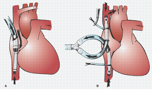
FIGURE 2.5. Methods of venous cannulation: bicaval and cavo-atrial or “two-stage.” A: Single cannulation of right atrium (RA) with a “two-stage” cavo-atrial cannula. This is typically inserted through the right atrial appendage. Note that the narrower tip of the cannula is in the inferior vena cava (IVC), where it drains this vein. The wider portion, with additional drainage holes, resides in the RA, where blood is received from the coronary sinus and superior vena cava (SVC). The SVC must drain through the RA when a cavo-atrial cannula is used. B: Separate cannulation of the SVC and IVC. Note that there are loops placed around the cavae and venous cannulas and passed through tubing to act as tourniquets or snares. The tourniquet on the SVC has been tightened to divert all SVC flow into the SVC cannula and prevent communication with the RA.


Potential for Venous Air Entry

It is now recognized that air entering the circuit through the venous system can pass through the membrane oxygenator and arterial filter and contribute to systemic gaseous microemboli (GME). Stock et al. (18) observed that approximately 60% of the GME in the line coming out of the venous reservoir reached the arterial line past a membrane oxygenator (Jostra Quadrox) and an arterial filter (Jostra Quart 40 µm), whereas Perthel et al. (19) found even more microbubbles (but about the same volume of microscopic air [“microair” or “foam”]) in the blood after passage through a membrane oxygenator and arterial-line microfilter (Jostra Quart HBF 140) as compared with the blood before the centrifugal pump. Leaks around the exit site of the venous cannulas from the atria or cavae are a frequent source of venous air entry; therefore, great care must be taken to make sure that the purse-string sutures are airtight. Placing a second suture around the atrial tissue and the cannula proximal to the initial purse-string suture, or a second precise purse-string suture, may correct this problem. This is an especially important problem when augmented venous return (kinetic or vacuum) and/or unitized minimal circuits are being used, but is probably a good practice for all cases. Monitoring for the presence of microair in the venous or arterial lines gives warning to the team that there is an air entrainment problem and quality assurance when the problem has been resolved (19,20,21). Stock et al. (18) showed that by completely eliminating all visible air from the venous cannulas and lines before initiating CPB they could reduce the amount of GME passing through the circuit by 98%.


Peripheral (Extrathoracic) Venous Cannulation

At times, venous cannulation is accomplished peripherally, usually through the femoral or iliac veins. This is used for emergency closed cardiopulmonary assist, for support of particularly ill patients before induction of anesthesia, for prevention or management of bleeding complications during sternotomy for reoperations, during minimal access surgery, and for certain types of aortic and thoracic surgery. The key to achieving adequate flow rates with peripheral cannulation is use of as large a cannula as possible and advancing the catheter
into the RA guided by transesophageal echocardiography (TEE), if available. Specially designed, commercially available (e.g., Medtronic BioMedicus, Inc., Eden Prairie, MN), long, ultrathin, nonkinkable, wire-reinforced catheters are available for this purpose. Insertion may be facilitated by the use of an internal stylet and guidewire. Jones et al. (22) documented flows of up to 3.6 L/min (25F) to 4.0 L/min (27 and 29F) with simple gravity drainage. Using another brand of femoral venous catheter (model Fem-Flex II, Research Medical, Inc.) and gravity drainage, Merin et al. (23) obtained flows of up to 2.5 L/min with 20F catheters and flows of 3.5 to 4.5 L/min with 28F catheters. This flow can be augmented by the use of kinetic or vacuum assistance, which is discussed in the subsequent text. Flow through various femoral venous cannulas augmented by gravity and applied suction have been discussed by Shann and Melnitchouk (10) and are summarized in Table 2.3.

Westaby (24) suggested that in cases where IVC drainage alone does not provide adequate venous return, adding a 32F cannula inserted into the SVC through a surgical approach to the right internal jugular (IJ) vein is effective. In contrast, Flege and Wolf (25) described using the right IJ vein as the sole source of venous drainage for conduct of CPB using percutaneously placed 21F 20-cm-long femoral arterial catheters (Medtronic DLP, Inc.) advanced into the RA and augmented venous drainage. Coaxial wire-reinforced polyvinyl chloride (PVC) bicaval femoral venous cannulas (“Carpentier”) (24-29F and 30-33F) are also available (DLP, Grand Rapids, MI). They possess two series of holes, one set near the tip (for draining the SVC) and another approximately 18 cm more proximally (for draining the IVC), with a nonperforated 18-cm segment designed to rest in the right atrium. This allows drainage of the SVC and IVC while isolating the RA by snaring the proximal SVC and IVC around the cannula; however, Tevaerarai et al. found it necessary to employ augmented venous return (kinetic) to achieve near full (93%) flow (26).


TABLE 2.3. Femoral venous cannula, estimated flow rates


Size (F)


Augmented max flow (L/min)a


Model


Manufacturer


17


2.6


BioMedicus one piece


Medtronic


19


3.5


BioMedicus one piece


Medtronic


19


3.8


BioMedicus multistage


Medtronic


21


4.0


BioMedicus one piece


Medtronic


21


4.5


BioMedicus multistage


Medtronic


22


4.6


Remote Access Perfusion (RAP)


Sorin


25


5.2


BioMedicus multistage


Medtronic


23/25


5.2


RAP


Sorin


a Approximate cardiopulmonary bypass flow with net (gravity + applied) negative pressure of -80 to -100 mmHg. Source: Modified from Table 5 of Shann K, Melnitchouk S. Advances in perfusion techniques: minimally invasive procedures. Semin Cardiothorac Vasc Anesth 2014;18(2):146-142; used with permission.


Impact of Persistent Left Superior Vena Cava

An LSVC is present in approximately 0.3% to 0.5% of the general population, but in 2% to 10% of patients with congenital heart disease and in up to 40% when such patients have abnormal situs. It usually drains into the coronary sinus and then into the right atrium (27,28,29,30,31). In approximately 10% of cases, usually associated with other congenital heart diseases, the LSVC drains into the left atrium. In some cases, there are defects in the wall between the coronary sinus and the left atrium, permitting intercommunication between the left atrium and RA (the so-called coronary sinus-type atrial septal defect [ASD]).

The presence of an LSVC should be suspected when a large coronary sinus is noted on echocardiography (differential diagnosis includes right-sided venous hypertension, tricuspid regurgitation, and stenosis of the ostium of the coronary sinus in the absence of an LSVC) (32). Sometimes the LSVC itself can be seen on echocardiography posteriorly and laterally to the left atrium above the atrioventricular groove beside the aorta. Its presence can be confirmed by injection of agitated saline echocontrast into a left arm vein or left IJ vein and
noting its passage into the coronary sinus before its arrival into the right atrium. The surgeon should suspect an LSVC when the (right) SVC looks small, and when the left innominate vein is small or absent.

The presence of an LSVC poses a number of problems during cardiac surgery. It may confuse and complicate passage of a pulmonary artery (PA) catheter or interfere with administration of retrograde cardioplegic solution (33). The latter is compromised because the coronary sinus is usually quite large in this circumstance and therefore the balloon on the retrograde catheter does not seal, and the cardioplegic solution leaks into the RA. Furthermore, the cardioplegia solution may run off into the persistent LSVC, and it will be diluted with systemic venous blood draining down the LSVC. Finally, the presence of an LSVC poses obvious problems if the right heart is to be entered, or with right heart decompression and adequacy of venous return if bicaval cannulation is used, because of the flow of the additional systemic venous blood into the right atrium.

If the right heart is not going to be opened and a single- or two-staged venous cannula is used for venous drainage and retrograde cardioplegia is not used, the presence of an LSVC poses no problems. However, if the right heart needs to be entered, several options are available. If an adequate-sized innominate vein is present (true in approximately 30% of cases), the LSVC can simply be occluded during CPB. However, one must be wary of the rare possibility of the associated anomaly of atresia of the coronary sinus, in which case the LSVC provides the main outlet for cardiac venous drainage, and occlusion of the LSVC could injure the myocardium (34,35). This condition should be suspected if the coronary sinus is not enlarged, by failure of echocontrast injected in the left arm or LSVC to enter the RA through the coronary sinus during TEE, and if there is evidence by echo-Doppler of reversed flow in the LSVC (i.e., away from the coronary sinus instead of toward it). Another obvious circumstance, in which the LSVC cannot be occluded despite the presence of an adequately sized innominate vein, is when there is an associated absence of the right SVC (true in approximately 20% of cases).

If the innominate vein is absent (true in approximately 40% of cases) or small (true in approximately 33% of cases), occlusion of the LSVC may cause serious venous hypertension and potentially cerebral injury or ischemia, in which case this should not be done without documenting acceptable venous pressure in the LSVC cephalad to the occlusion. Otherwise, some other arrangement must be made to provide drainage of the LSVC. Use of cardiotomy suction in the coronary sinus ostium may be adequate, but cannulation, usually through a cannula passed retrograde into the LSVC through the ostium of the coronary sinus, is preferred, with a caval tape (tourniquet) placed around the LSVC. Alternatively, a cuffed caval cannula or endotracheal tube may be used (28). A caval cannula can also be placed directly into the LSVC through a purse-string suture placed externally. Finally, in small infants, induction of deep hypothermia with CPB cooling using a single venous cannula followed by circulatory arrest obviates the need for extra cannulation of the LSVC.


Augmented Venous Drainage

Early in the history of CPB, suction pumps (roller or finger) were used for venous drainage, but because they were difficult to control, these were discarded in favor of the simpler and effective gravity siphon method described earlier. During the last two decades, there has been a renewed interest in the use of regulated suction to overcome the resistance of longer and/or narrower venous cannulas used during limited (transthoracic) access or peripheral venous (e.g., jugular or femoral veins) access. With these narrower and longer venous cannulas, gravity siphon alone may not provide adequate flow for full CPB even with a maximal height differential between the patient and the venous reservoir. Augmented venous return has also been used to reduce circuit volume by being able to raise the pump oxygenator (e.g., minimized circuits, explained later) up to the level of the patient.

Three methods to augment the venous return have been described. One is to place a roller pump in the venous line between the venous cannula and the venous reservoir (36). This carries a high risk of generating excess negative pressure and collapsing the RA or great veins around the cannula tip and requires constant attention and adjustment of the roller pump flow rate; so this technique is rarely used. Currently two methods are employed and have been reviewed recently by Shann and Melnitchouk (see Fig. 2.6) (10). One utilizes a kinetic (centrifugal) pump in the venous line and is referred to as kinetic- or centrifugal-assisted venous drainage (KAVD or CAVD) (37). The other method involves applying a regulated vacuum to a closed hard-shell venous reservoir attached to the venous line and is referred to as vacuum-assisted venous drainage (VAVD) (38,39). This system is relatively simple and does not require regulation of a second pump.

With KAVD a second systemic pump (centrifugal or roller) then pumps blood out of the venous reservoir through the oxygenator and to the patient. Fried et al. (40) described the use of a single pump for KAVD. Using their method, one centrifugal pump both aspirates venous blood and pumps it to the patient. This requires that the venous reservoir be excluded from the venous line. This method reduces the problem of balancing the flow of two pumps but runs the risk of systemic air embolization. The use of a single centrifugal pump for both augmenting venous return and providing systemic flow (with no intervening venous reservoir) is employed in some minimized circuits. (See subsequent section).

Use of any of these systems requires careful regulation of the degree of negative pressure applied to the venous line. This is best accomplished by monitoring the pressure in the venous line approximately 10 cm before the inlet to the venous pump (roller or kinetic) or in the hard-shell reservoir (if using a
vacuum-assisted system). The negative pressure (or vacuum) measured at this site should not exceed -60 to -100 mmHg (37), but usually -20 mmHg is sufficient. Jones et al. (41) found that vacuum exceeding 40 mmHg increased the amount of GME in a CPB model. It is also desirable to observe the RA directly or through TEE. When the vacuum-assisted system is used, the degree of vacuum applied should be controlled with a vacuum regulator that can be adjusted and can display low levels of suction in 10-mmHg increments. It is important that vacuum should never be applied when there is no forward blood flow through the oxygenator, to prevent air from being pulled across the microporous membrane into the blood path (“bubble transgression”) (42). For this reason and to prevent other causes of air embolization, it is recommended that the venous lines and cannula be filled with fluid, and that vacuum assistance should not be applied until after initiation of CPB. The reservoir should also be open to the atmosphere when vacuum is not being applied to prevent over-pressurization of the venous reservoir with reduction of venous return and risk of retrograde or antegrade air embolization. The venous reservoir should have a low positive (approximately ±5 mmHg) and a high negative (approximately -100 mmHg) pressure relief valve. Usually, adequate venous drainage is achieved with speeds of 1,000 to 1,200 revolutions per minute (rpm) of the kinetic pump or application of 20 mmHg vacuum to the venous reservoir.


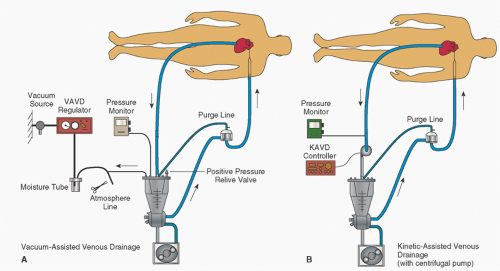
FIGURE 2.6. VAVD and CAVD augmented venous drainage. VAVD, vacuum-assisted venous drainage; CAVD, centrifugal-assisted venous drainage. (Figure 1 from Shann K, Melnitchouk S. Advances in perfusion techniques: minimally invasive procedures. Semin Cardiothor Vasc Anesth 2014;18(2): 146-152,2014;18(2): 146-152, used with permission.)

When a vacuum-assisted system is used with a closed reservoir, the degree of vacuum within the reservoir is influenced not only by the amount of vacuum applied to the system but also the relative flow of blood and air into the reservoir (from the venous line and cardiotomy suction and vents) and blood out of the reservoir (by the systemic pump).

There are a number of potential problems and risks associated with the use of augmented venous drainage methods. Excessive negative pressure may cause hemolysis because red blood cells (RBCs) are more easily damaged by negative than positive pressure (43,44,45), although Mueller et al. (46) were not able to detect increased RBC damage associated with 6 hours of CPB in calves with vacuum-assisted versus gravity venous drainage. There may also be collapse of right atrial, tricuspid valve, or venous structures around the cannula tip, resulting in impaired venous return and “chattering” in the venous line and possible damage to cardiovascular structures. Application of additional negative pressure (beyond gravity) increases the risk and amount of macro- and microair aspiration from around the venous cannula insertion sites (loose or imprecise purse-string sutures), or through holes in the walls of the RA or great veins. Air may also enter through a patent foramen ovale (PFO) if the left heart is open, or through any intravenous lines or introducers that may be in place (these should be closed or placed in occlusive infusion pumps during augmented venous return). Any aspirated air may cause an air
lock or can de-prime a centrifugal pump and stop blood flow, or enter the venous reservoir, and can then pass into the arterial circuit and contribute to systemic air embolization and cerebral injury (47,48,49,50). As mentioned earlier, application of an extra ligature around the atrial tissue where the venous cannula exits is advocated to reduce the risk of air aspiration. If vacuum is applied to the closed reservoir system during a no-flow state, there is the theoretic risk of pulling air across the microporous membrane into the blood path, with subsequent systemic air embolism. If the venous reservoir is closed to atmosphere when vacuum is not being applied, the venous reservoir can become overpressurized and reduce venous return while increasing the risk of retrograde or antegrade air embolization (51). If intracardiac septal defects or PFO are present, air pushed into the right heart can lead to massive paradoxical systemic air embolization (49,52). When a pump is being used to augment venous return, there is also a potential for imbalance of flow between the venous drainage and the systemic flow pump, resulting in a change in intravascular volume in the patient or a risk of systemic air embolism. Therefore, the use of assisted venous drainage requires application of special safety monitors and devices, which do not always work (51), and adherence to detailed protocols, and the perfusionist must be even more attentive than when using conventional gravity siphon drainage (1,52). To minimize the risk of retrograde air embolism into the atrium through accidental pressurization of the venous reservoir, it is not prudent to apply vacuum if the venous lines are not full of fluid (as might be done for retrograde autologous priming [RAP]), nor at the time of initiating CPB. It is best to wait until extracorporeal circulation is well established before applying vacuum to the system.

Shann and Melnitchouk (10) recommend the following practices to safely utilize augmented venous return: (1) when using VAVD, use of an approved vacuum regulator (e.g., Boehringer model 3930); (2) total negative pressure (gravity + applied vacuum) should not be more than 100 mmHg; (3) use the minimum amount of applied negative pressure to achieve the desired flow; (4) monitor venous reservoir positive and negative pressure with visual and audible alarms; (5) when using a centrifugal arterial pump, incorporate a one-way valve between the venous reservoir and oxygenator; (6) eliminate venous air entrainment in all clinical situations.


Complications Associated with Achieving Venous Drainage

These include atrial dysrhythmias, laceration and bleeding of the atrium, air embolization (especially if the atrial pressure is low, which could cause systemic embolization with potential right-to-left shunts), laceration of the vena cavae (the IVC is particularly prone to this), and malposition of the tips (or atrial portion of the cavo-atrial catheter), including inserting the tips into the azygous, innominate, or hepatic veins or across an ASD into the left heart. Placement of the low atrial purse-string suture for cannulation of the IVC requires retraction of the heart, which may have adverse hemodynamic consequences and is sometimes deferred until the patient is placed on bypass with a single cannula (SVC). Placing tapes around the cavae may lacerate the cavae themselves or branches off the cavae or, when encircling the SVC, the right PA. Once the venous cannulas are in place, they may interfere with venous return and cardiac output until CPB is initiated. Placing venous cannulas may displace the central venous or PA catheters inserted for hemodynamic monitoring. Caval tapes may occlude these lines and, conversely, their presence may prevent tight caval occlusion by the tapes. Further, these monitor lines may become caught in the atrial purse-string sutures, causing malfunction and preventing their removal (53). Finally, the cavae may become obstructed when purse-string sutures placed in the cavae are closed after cannula removal (54).


Causes of Low Venous Return

Reduced venous drainage may be due to reduced venous pressure, inadequate height of the patient above the venous reservoir, malposition of the venous cannulas (sometimes due to surgical manipulation of the heart), or obstruction or excess resistance in the lines and cannulas. Inadequate venous pressure may be caused by venodilation with drugs (e.g., nitroglycerin, inhalation anesthetics) or hypovolemia. Other causes of low venous return include kinks, air locks, and cannulas that are too small. An air lock occurs in the venous line when sufficient air enters the line to de-functionalize the siphon. This is most often due to dislodgment of a venous cannula. When this occurs, the arterial pump must be stopped immediately to prevent emptying the venous reservoir and possible air embolism until the air lock is eliminated. The latter is accomplished by clamping the venous line near where it enters the venous reservoir and then the venous lines are refilled with fluid, or the air is moved out of the venous line by serial elevation of the line so that the air progressively moves downstream and then allowed into the venous reservoir. During rewarming, the tendency for kinking of cannulas is potentially aggravated by softening of the tubing and/or surgical manipulation of the heart.


Arterial Cannulation


Cannulas

Many different types of cannulas made of various materials are available (Figs. 2.7 and 2.8). Some that are designed for insertion into the ascending aorta have right-angled tips, some are tapered, and some have flanges to aid in fixation and to prevent the introduction of too great a length into the aorta. The arterial cannula is usually the narrowest part of the ECC. High flow through narrow cannulas may lead to high pressure gradients, high velocity of flow (jets), turbulence, and cavitation, with undesirable consequences, which are discussed later.

Hemodynamic evaluations of arterial cannulas have traditionally been based on measurement of the pressure drop.


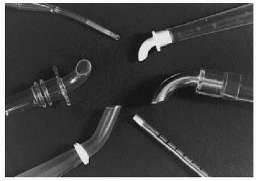
FIGURE 2.7. Conventional arterial cannulas. (From Kaplan JA, Reich DL, Savino JS, et al. Kaplan’s cardiac anesthesia. 6th ed. Philadelphia, PA: Elsevier, 2011, used with permission.)


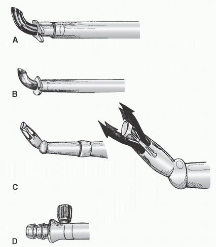
FIGURE 2.8. Other arterial cannulas. A: Metal-tipped right-angled cannula with plastic molded flange for securing cannula to aorta. B: Similar design but with a plastic right-angled tip and molded flange. C: (Left) Diffusion-tipped angled cannula designed to direct systemic flow in four directions to avoid a “jetting effect” that may occur with conventional single-lumen arterial cannulas. An inverted cone occludes the tip. (Right) Drawing with arrows depicts the flow patterns. D: Integral cannula connector and Luer port (for de-airing) incorporated into some arterial cannulas; newer arterial cannulas may contain a self-venting cap (not shown) for removal of air during insertion.

A useful descriptive characteristic of an arterial cannula is its “performance index” (pressure gradient vs. OD at any given flow) (55). The narrowest portion of the catheter that enters the aorta should be as short as compatible with safety, and thereafter the cannula size should enlarge to minimize the gradient. Long catheters with a uniform narrow diameter are undesirable. The use of thin metal or hard plastic (e.g., polycarbonate) for the tip provides the best ID-to-OD ratio. Pressure gradients exceeding 100 mmHg are associated with excessive hemolysis and protein denaturation (56). Therefore, it is preferable to select a cannula that will provide adequate flow with no more than 100-mmHg pressure gradient. Drews et al. (57) suggested that in small-sized cannulas, the right-angle configuration (as compared with straight configuration) may aggravate hemolysis. New approaches to hemodynamic evaluation of arterial cannula include velocimetry (58) and detailed analysis of flow patterns using laser Doppler anemometry (59), color Doppler ultrasound, and high-field magnetic resonance imaging (MRI) (60), but the clinical relevance of these studies is yet to be demonstrated. Shann and Melnitchouk (10) recommend use of a 6-mm arterial cannula for patients ≤2 m2, a 7-mm cannula for patients 2.1 to 2.4 m2, and 8-mm cannula for patients ≥2.5 m2.

The jetting effect produced by small cannulas may damage the interior aortic wall, dislodge atheroemboli (“sandblasting”) and cause arterial dissections, and disturb the flow into nearby vessels. Several new designs of aortic cannulas have been introduced to disperse the flow out of the cannulas tips to reduce the sandblasting effect. Muehrcke et al. (59) described an aortic cannula (Soft-Flow cannula, Sarns, Ann Arbor, MI) that had a closed tip (with an internal cone) and multiple side holes and was designed to reduce exit forces and velocities to reduce these adverse jet effects (Fig. 2.8C). Hemolysis rates were similar, whereas pressure gradients were intermediate compared with a number of other cannulas in common use. However, this cannula is no longer being marketed. Edwards Lifescience Research Medical (formerly Baxter RMI, Midvale, UT) distributes the dispersion cannula, which is designed to emit a soft fan-shaped jet of lower velocity (61). Grooters et al. (62) compared, in three patients each, the exit jet pattern and velocities (using TEE) between an 8-mm soft-flow cannula, an 8-mm dispersion cannula, and a 7.3-mm end-hole steel-tip cannula (Sarns). At similar systemic flow rates (approximately 5.2 L/min), perfusion line pressures were similar, but jet velocities at 1-, 2-, and 3-cm distances were significantly lower with the dispersion cannula compared with the other two, whereas the velocity at 1 cm was slightly higher and at 2 and 3 cm somewhat lower with the soft-flow cannula compared with the end-hole cannula. (See comparative photographs of the jets exiting these three types of cannulas in the paper by Weinstein (63).) Gerdes et al. (64) have described an aortic cannula (Medos X-flow) that incorporates a helical stator in its tip to reduce the jet effects as documented by in vitro studies, and Scharfschwerdt et al. (65) have described a new
prototype cannula tip that contains circular lamellae (Stockert Instrumente, Munich, Germany), designed to produce a divergent diffuse flow pattern. These authors compared the hydrodynamics of this new catheter with a standard end-hole cannula (Argyle THI) and the aforementioned Sarns Soft-Flow and Medos X-flow cannulas. The new cannula exhibited the lowest pressure gradient, lowest back-pressure (pressures at various distances and locations beyond the tip), and a broad uniform centric flow dispersion pattern. Reports of clinical studies with the Medos and prototype Stockert arterial cannulas have not been found.

White and colleagues (66) developed a novel expanding funnel tip cannula and compared it with a 45 ° straight-tip, 80° angled straight-tip, Sarns Soft-Flow (Terumo Cardiovascular Systems Corp, Ann Arbor, MI), and the Dispersion cannula (Research Medical, Inc.) regarding pressure drop, exit velocity mapping using MRI, flow pattern visualization, and athero-embolization (particle dislodgment). They reported that the funnel-tipped cannula exhibited lower pressure drop, exit velocity and least particle dislodgment compared to the other cannulae. They found that the Soft-Flow cannula had the next lowest pressure drop but had twice the exit velocity and particle dislodgment as their Funnel-tipped cannula and that the Dispersion cannula reduced neither velocity or particle dislodgment as compared with standard tip cannulae.

Menon and colleagues (67) described their analysis of neonatal arterial cannulas. Jet wake analysis was performed using direct numerical simulation computational fluid dynamics (CFD) in a cuboidal test rig and particle image velocimetry. Blood damage indices were assessed in an aortic model. They described a novel diffuser type cannula for improved jet flow control and decrease blood damage but also noted that surgically relevant cannula orientation may be important factor in hemodynamic performance.

Brodman et al. (55) evaluated 29 different types of arterial cannulas. They found that an 8-mm OD high-flow aortic arch cannula (model 15235, 3M Healthcare, Inc., Ann Arbor, MI) and an 8-mm OD aortic cannula with or without flange (models 1858 and 1860, CR Bard, Billerica, MA) were best (gradient <50 mmHg at flows of 5 L/min), whereas several others were unacceptable (gradient >100 mmHg at flows of 4 L/min). For cannulas not studied by them, one should refer to the gradient-flow data provided by the manufacturer, or conduct bench-top tests. Unfortunately, the data of Brodman et al. may underestimate the clinical gradients because they used water rather than blood or a blood analog as the fluid in their studies. Size and shape of aortic cannulas did not influence the rate of transcranial Doppler (TCD)-detected microemboli in one study (67b).


Special-Purpose Arterial Cannulas

An innovative dual-stream aortic perfusion catheter (“Cobra”) was developed to reduce cerebral embolization and permit selective cerebral cooling and was evaluated clinically but has not been approved for use in the United States (68,69). The Aegis aortic cannula (Cardeon Inc., Cupertino, CA) was a modification of the Cobra dual-stream catheter, which had only a single lumen (70). It is also no longer available for clinical use.

Another novel 24F OD arterial cannula, the Embol-X, incorporates a side port through which a heparin-coated 120-µm mesh butterfly net type filter can be inserted to catch particulate emboli exiting the ascending aorta (Embol-X, Embol-X Inc., Mountain View, CA) (71). Hydrodynamically, this catheter produces 50% higher pressure gradient and jet pressure than conventional cannulas of comparable size (72). In a multicenter European case series of 185 patients at high risk for neurologic complications, the International Council of Emboli Management (ICEM) Study Group observed a lower risk of type I outcome compared with the Multicenter Study of Perioperative Ischemia (McSPI) data (73). However, the same group reported a multicenter randomized control trial (RCT) involving 1,289 patients older than 59 years (mean 72 years) undergoing CABG (86%) or valve surgery in the United States (74). Although particulate emboli were identified in 97% of the filters and its use was not associated with any complications, there was no difference in incidence of adverse neurologic, gastrointestinal (GI), renal, or composite events. Horvath et al. (75) documented the number (0-74 average 8), size (area 1-188 average 6 mm2), and nature (79% fibrous atheromata) of the emboli captured in 98% of 2,297 patients following use of this catheter. Christenson et al. (76) advocate deploying the filter of this catheter (EMBOL-X Slim Protection System, Edwards) both just before applying and again just before removing the aortic clamp for maximal effectiveness, although the former retrieved significantly more embolic particles. Gerriets et al. (77) observed no difference in cognitive function or in number of small ischemic brain lesions (per MRI) in a small RCT (43 vs. 50 patients) with use of the Embol-X device. This device clearly captures emboli, but high-level evidence of clinical benefits (or adverse effects) is wanting.

In their evidence-based appraisal, Hogue and colleagues (78) concluded that the evidence supporting the use of modified arterial cannula to improve neurologic outcome was “indeterminate”.


Connection to the Patient


Ascending Aorta

In the early days of CPB, arterial inflow was through the subclavian or femoral artery (79), but currently, as first proposed by Nunez and Bailey in 1959 (80), it is usually through a cannula inserted into the ascending aorta The advantages of this approach over the femoral (or iliac arteries) (Table 2.4) include ease, safety, and the fact that it does not require an additional incision. The surgical technique for aortic cannulation has been reviewed in detail by others (9,17,81,82). The site for cannulation is selected on the basis of the type of cannula to be used, the operation planned (i.e., how much of the
ascending aorta is available), the quality of the aorta, and the surgeon’s preference.


TABLE 2.4. Comparison of arterial cannulation sites


Characteristic


Ascending aorta/arch


Femoral artery


Axillary/subclavian


Accessibility


Readily


Requires separate incision


Requires separate incision


Cannula size


Relatively unlimited


Limited


Limited


Risk of malperfusion of arch vessels


Yes


No


Possible


Perfusion direction


Antegrade


Retrograde


Antegrade


Risk of limb ischemia


No


Yes


Yes


Aortic dissection incidence


0.01%-0.1%


0.2%-1.0%


˜0.75%


Local artery complications


No


Yes


Yes


Wound infection 0%


˜4%


<1%


Advantages


Convenient Low risk of dissection


Allows peripheral cannulation Allows cannulation before sternotomy in high-risk patients


Less risk of atheroembolism Less malperfusion during surgery for aortic dissection Permits selective antegrade cerebral perfusion


Disadvantages


Atheroembolism May not be acceptable (e.g., Porcelain aorta)


Retrograde dissection Limb ischemia Local wound complications


Separate incision Injury to brachial plexus and artery When aortic cannulation not feasible or desirable


Indications


Most cases


When aortic cannulation not feasible or desirable Peripheral cannulation before Induction of general anesthesia Emergency “rescue” cannulation


When aortic cannulation not feasible or desirable Aortic dissection surgery


Contraindications


Disease of Asc. Aorta


Occlusive disease in vessel Extensive atheroma in descending aorta or arch


Occlusive disease in vessel


Atherosclerosis with or without calcification frequently involves the ascending aorta and poses problems with arterial cannulation and application of clamps and vascular grafts. Dislodgment of atheromatous debris either by direct mechanical disruption or from the “sand-blasting” effect of the jet coming out of the arterial cannula is thought to be a major cause of perioperative stroke (83,84,85). Atherosclerosis is also considered a risk factor for perioperative aortic dissection (86) and postoperative renal dysfunction (87).

Traditionally, surgeons have relied on palpation to detect these changes and select sites for cannulation, cross-clamping, and so on, and this should continue to be one component of the evaluation of the aorta. Mills and Everson (88) recommend using a 10- to 20-second period of venous inflow occlusion to reduce systemic arterial pressure to 40 to 50 mmHg to improve the reliability of palpation of the ascending aorta. However, palpation is much less sensitive and accurate than epivascular ultrasonic scanning (89,90,91,92). Details on how to perform an intraoperative epiaortic ultrasonographic examination are provided in the 2007 ASE/SCA guideline (93). Unfortunately, TEE, which is more convenient, is not as sensitive because of limited views it can provide of the more distal ascending aorta where cross-clamping and cannulation are performed (91,92,94). However, some believe it can be used as a screening method to determine which patients need epiaortic scanning. If no significant atherosclerosis is detected in the ascending, transverse, or proximal descending aorta, it has been suggested that epiaortic imaging is not necessary (95), but others disagree (95b).


Epiaortic and transesophageal scanning should be considered complementary (92). Beique et al. (85) suggested using epiaortic scanning in all patients who have a history of transient ischemic attacks, strokes, severe peripheral vascular disease, and palpable calcification in the ascending aorta, calcified aortic knob on chest X-ray, those older than 60 years, and those with TEE findings of moderate aortic atherosclerosis. Others advocate epiaortic scanning of the ascending aorta in all patients older than 50 years (96). Three evidence-based guidelines recommend that “intraoperative TEE or epiaortic ultrasound scanning of the aorta should be considered (Class IIa, level of evidence B)” (97), that “epiaortic ultrasound-guided changes in surgical approach… (provide) neuroprotection during CPB (IIb)” (78), and that “routine epiaortic ultrasound scanning is reasonable to reduce the incidence of atheroembolic complications (Class IIa, level of evidence B)” (98). If atherosclerosis is detected, then the sites for insertion of cannulas, grafts, and application of vascular clamps are modified. If extensive atherosclerosis precludes arterial cannulation in the ascending aorta, then the femoral route should be considered (see subsequent text). However, in this case, the transverse and descending aorta should be evaluated by TEE to rule out extensive atheroma that might be embolized into the brain or elsewhere with retrograde flow from a femoral cannula. If such is the case, then axillary-subclavian or innominate artery cannulation should be considered. Studies using historical control subjects suggest improved neurologic outcome with echocardiographic-based modification of surgical techniques in handling the ascending aorta (85,90,99).

If atheroma is extensive in the ascending or transverse aorta, some clinicians have suggested using a long arterial cannula that is inserted in the ascending aorta and threaded around into the proximal descending aorta to reduce the “sand-blasting” effect (100). Others have advocated doing an endarterectomy under deep hypothermic circulatory arrest (DHCA) if severely protruding or mobile atheromas are detected (101), but in one study of 268 patients with severe protruding atheromas, aortic arch endarterectomy (in 43 patients) was associated with a higher stroke rate (35% vs. 12%) and mortality (19% vs. 12%) than when endarterectomy was not performed (102). In addition, endarterectomy was found, on multivariate analysis, to be an independent predictor of stroke (Odds Ratio [OR] 3.6) (103).

If the ascending aorta is totally calcified and rigid (so-called “porcelain” aorta), then entirely different strategies for cannulation and surgery must be used. These include no clamping of the ascending aorta, use of an alternate site for arterial cannulation, performing the operation “off-pump” if feasible, or, in selected cases, graft replacement or endarterectomy of the ascending aorta during DHCA (96,104). Unfortunately, graft replacement of the atherosclerotic ascending aorta is intrinsically a high-risk procedure (105). If there is no intraluminal debris, Liddicoat et al. (106) used an intraluminal balloon designed for port-access surgery, which is inserted through a purse-string suture in an atherosclerosis-free portion of the aortic arch to occlude the aorta. Others used a urinary (Foley) catheter in a similar manner (107).


Cannulation of the Ascending Aorta

Many surgeons insert two concentric purse-string sutures into the aortic wall. Surgeons differ as to whether these should be shallow, deep, or full-thickness bites. Unal et al. (108) discuss in detail the placement of the aortic purse-string suture and extol the virtues of a tangential suture technique (TST). Most surgeons then incise and dissect away the adventitia within the purse-string suture. Most avoid using a partial occluding clamp, except in pediatric patients, to minimize clamp trauma to the aorta. Optimal arterial blood pressure during cannulation (mean arterial pressure of approximately 70 to 80 mmHg, systolic pressure of approximately 100 to 120 mmHg) is probably important: if too high, there may be a greater chance of tears and dissection and blood loss and spray; if too low, the aorta tends to collapse, it is harder to make an incision and insert the cannula, and there is a greater risk of damaging the back wall of the aorta. An appropriately long full-thickness incision is then made, and the leak is controlled with a finger or by approximating the adventitia or by simultaneously inserting the cannula.

Dilators are sometimes used. If a right-angled cannula tip is used, it is often initially directed toward the heart and then rotated 180° to confirm intraluminal placement. Brief vigorous back bleeding out of the open cannula is then allowed to eliminate air or atheromatous debris and to further confirm intraluminal placement. This can be additionally confirmed by noting a pulsatile pressure approximating radial artery pressure in the CPB circuit arterial-line pressure monitor. Proper position of the cannula tip is critical. Most surgeons insert only 1 to 2 cm of the tip into the aorta and direct it toward the middle of the transverse arch to avoid entering the arch vessels (Fig. 2.9). Grooters et al. (61) point out that atherosclerosis is often more severe in the aortic arch, against which the jets from these short cannulas are directed, which may become the source of cerebral emboli, especially when the ascending aorta is relatively free of atherosclerosis. Barbut et al. (109) noted high-grade plaque with greater frequency in the arch (18%) than in the ascending aorta (5.3%), and Weinstein (63) has attributed the fact that more strokes occur in the left than the right cerebral hemisphere to jets striking atheroma in the arch. To minimize this risk, Grooters et al. (61) have advocated directing the jet toward the ascending aorta (when it is free of atherosclerosis) and/or the use of dispersion type arterial cannulas. As mentioned earlier, others have advocated threading a long cannula into the proximal descending aorta to reduce the velocity and turbulence in the aortic arch to reduce the “sand-blast” effect and emboli (100), although atheromata may be dislodged by the act of inserting this cannula through the intervening thoracic aorta. Mullges et al. (110), in
a small RCT of 60 patients undergoing CABG, found that using an elongated cannula with the tip in the descending aorta, as compared with a short cannula in the ascending aorta, was associated with fewer microembolic signals (TCD), but there was no difference in cognitive performance (seven neuropsychological tests) 9 days postoperatively.


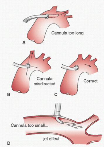
FIGURE 2.9. Aortic cannulation problems. A: cannula extends into carotid owing to excessive length causing excessive carotid flow. B: Cannula is directed into innominate causing hyperperfusion of right carotid and hypoperfusion of left. C: Correct cannula direction. D: Cannula diameter too small; high velocity jet may damage intima or cause decrease flow (venturi effect in some arch branches. (Hensley FA, Martin DE, Gravlee GP, eds. A practical approach to cardiac anesthesia. 5th ed. Philadelphia, PA: Wolters Kluwer, 2013, used with permission.)

After the arterial cannula is inserted, a test infusion with the systemic pump through the arterial line before initiating CPB is recommended (regardless of location of the arterial cannula, i.e., ascending aorta/arch, femoral artery, axillary/subclavian, etc.). A higher-than-expected pressure in the circuit arterial line warns of possible dissection and may help avoid a more extensive dissection. Another method to assess this was described by DeBois and colleagues (111). The lack of negative flow or a flow of <500 mL/min during retrograde arterial priming suggests cannula misplacement or occlusion.

Complications of aortic root cannulation include inability to introduce the cannula (interference by adventitia or plaques, too small an incision, fibrosis of the wall, low arterial pressure); intramural placement; dislodgment of atheroemboli, air embolism from the cannula, injury to the back wall of the aorta; persistent bleeding around the cannula or at the site after its removal; malposition of the tip (Fig. 2.9), or also to a retrograde position possibly even across the aortic valve, against the vessel wall, or into the arch vessels; abnormal cerebral perfusion; obstruction of the aorta in infants; aortic dissection; and high CPB arterial-side line pressure. High CPB circuit arterial-line pressure may be a clue to malposition of the tip against the vessel wall or into an arch vessel, cannula occlusion by the aortic cross-clamp, aortic dissection, a kink in the inflow system, an arterial-line clamp that is still on, or the use of too small a cannula for the intended CPB flow.

Inadvertent cannulation of the arch vessels or directing the jet into an arch vessel may cause irreversible cerebral injury and reduced systemic perfusion. Suggestive evidence includes high systemic line pressure in the CPB circuit; high pressure in the radial artery if supplied by the inadvertently cannulated vessel (or low pressure if not supplied by the cannulated vessel); unilateral facial blanching when initiating bypass with a clear priming solution; asymmetric cooling of the neck during perfusion cooling; and unilateral hyperemia, edema, petechiae, conjunctival tearing, or dilated pupils. Before CPB, palpation of the carotid arteries may reveal asymmetric pulsation (reduced on the cannulated side) and the opposite may be observed during pulsatile bypass (increased pulsation on the cannulated side). Before CPB, the radial artery catheter may reveal sudden damping if the cannula is inserted in the arch vessel supplying the monitored radial artery.

It has been suggested that the Coanda effect (in which a jet stream adheres to the boundary wall and hence produces a lower pressure along the opposite wall) may be associated with carotid hypoperfusion (112). This has been shown experimentally and may account for some cerebral dysfunction after CPB using aortic cannulation. Salerno et al. (113) detected major electroencephalographic abnormalities due to malposition of a cannula in 3 of 84 patients undergoing arch perfusion, possibly on the basis of the Coanda effect. Recently, a number of groups have studied this in mock circulations. Kaufmann and colleagues (114) studied the impact of cannula position on flow distribution utilizing CFD validated by particle imaging velocimetry. They found that direction of the cannula jet and its distance from a branch vessel could result in localized retrograde flow from a Venturi effect. Tokuda and colleagues (115) have also used CFD to analyze blood flow in the aortic arch during CPB, and Menon et al. (116) showed that neonatal cannula orientation could induce backward flow due to Venturi effect.

Antegrade aortic dissection (Table 2.5) associated with ascending aortic cannulation has been reported in 0.01% to 0.09% of cases (82,86,117,118,119,120). Aortic dissection should be suspected when any of the following are observed: a sudden decrease in both venous return and arterial pressure, excessive loss of perfusate, increased circuit arterial-line pressure, evidence of decreased organ perfusion (oliguria, dilated pupil, electroencephalographic changes, electrocardiographic evidence of myocardial ischemia), blue discoloration of the aortic
root (because of intramural hematoma), and bleeding from needle or cannulation sites in the aortic root. Subadventitial hematomas tend to be less extensive and softer, and usually resolve when incised. TEE and/or epiaortic ultrasound scanning are useful in diagnosing aortic dissection (93,119,120,121,122).


TABLE 2.5. Ascending aortic dissection complicating cardiac surgery


Murphy et al. (86)


Gott et al. (118)


Still et al. (117)


Combined


Year published


1983


1990


1992


Institution


Emory


Emory


MGH


Years covered


1971-1981


1982-1988


1982-1990


1971-1990


Total cases


6,943


11,145


14,877


32,965


Dissectionsa


24 (0.35)


27 (0.24)


24 (0.16)


75 (0.23)


Site of origin


Aortic cannulationa


4 (0.06)


10 (0.09)


10 (0.07)


24 (0.07)


Partial occlusion clamp


8


3


7


18


Aortic cross-clamp


1


4


8


13


Proximal SV anastomosis


4


2


1


7


Cardioplegia cannula


2


5


7


Vent site


1


1


Aortotomy


2


2


Unknown or other


3


2


1


6


When recognized


Operating room


15


27


20


62


Postoperatively


9


4


13


Mortality


If recognized in operating room


33%


15%


20%


21%


If recognized postoperatively


78%


50%


60%


Values are number of cases or incidents unless otherwise noted.


MGH, Massachusetts General Hospital; SV, saphenous vein.


a Values are number of incidents, with percentages in parentheses.


Gott et al. (118) and Still et al. (117) have discussed iatrogenic aortic dissection in detail. Management usually involves prompt cessation of CPB, recannulation distal to the dissection (usually femoral but occasionally into the distal aortic arch), induction of deep hypothermia, and a period of circulatory arrest while the aorta is opened and the extent of the injury analyzed and repaired by direct closure, use of a patch, or replacement of the ascending aorta with a tubular graft. Occasionally, small injuries can be repaired off CPB by closed
plication (118), but such repairs may fail early or later and therefore graft replacement is generally favored (124,120). Survival of those cases recognized and treated in the operating room has ranged from 66% to 85%. When not recognized until postoperatively, survival has been 50% or less (Table 2.5).

False aneurysms, which may rupture or become infected, are late complications of aortic cannulation (123,124). In a review of the literature (123) and the experience of a single institution (124), the arterial cannulation site was found to be the source of approximately one third of the ascending aortic aneurysms that follow cardiac surgery, of which approximately 40% were infected. The mortality of such complications was approximately 50%.


Femoral Arteries (See Table 2.4)

Cannulation of the femoral or iliac arteries (exposed through a retroperitoneal suprainguinal approach) is indicated when there is an aneurysm of the ascending aorta or when it is otherwise unsatisfactory for cannulation. This may also be indicated when there is inadequate space available due to multiple procedures involving the ascending aorta, for peripheral cannulation under local anesthesia in unstable patients, during reoperations prophylactically, when bleeding complications occur during reentry, or when an antegrade dissection complicates aortic cannulation. Femoral cannulation requires a second incision and limits the size of the cannula that can be used. Hence, the adverse consequences of fluid jetting effects and high pressure gradients are more likely. Lees et al. (125) found no difference in the distribution of blood flow and vascular resistance between retrograde (femoral artery infusion) and antegrade (aortic root infusion) flow in monkeys. Shann and Melnitchouk (10) made recommendations for size and model and maximal flow rates of various femoral artery cannulas based on patient’s size and these are summarized in Table 2.6.

Femoral cannulation is associated with many complications (23,113,126) including trauma to the cannulated vessel, such as tears, dissection, late stenosis or thrombosis, and bleeding; lymph fistula; infection; embolization; and limb ischemia. Muhs et al. (127) reported their experience with five (0.7% incidence) arterial injuries early (<30 days) following femoral perfusion utilizing the port-access system in 739 patients. Because the retrograde perfusion cannula usually totally occludes the direct blood supply to the cannulated limb, ischemic complications (acidosis, compartment syndrome, muscle necrosis, and neuropathy) may develop if cannulation exceeds 3 to 6 hours (128,129,130). The risk of distal ischemia can be minimized by placing a Y-connector or Luer-lock port in the arterial line and attaching a smaller cannula (e.g., 8-14F pediatric arterial cannula) which is then inserted distally through the same arteriotomy (130) or an 8.5F introducer catheter inserted into the distal superficial femoral artery using the Seldinger technique (131) to maintain perfusion of the leg. Alternately, VanderSalm (132) advocated suturing a 10-mm polytetrafluoroethylene graft end-to-side on the common femoral artery into which the 24F femoral cannula is inserted. This latter technique not only prevents lower extremity ischemia but also may reduce risk of arterial injury and retrograde dissection. Use of a coated Dacron graft may be associated with less bleeding. If distal limb perfusion is used and the ipsilateral femoral vein has also been cannulated, then a method to provide better venous drainage of that limb is suggested to reduce edema. Edema can be minimized either by not taping the vein around the cannula (130) or by placing a second (12F) venous cannula through the saphenous vein into the distal femoral vein (133). If limb ischemia does occur, Beyersdorf et al. (134) described a method of controlled limb reperfusion to improve outcome.


TABLE 2.6. Femoral artery cannula, estimated flow rates


BSA (m2)


Size (F)


Max flow (L/min)


Model


Manufacturer


≤1.3


15


2.5


BioMedicus


Medtronic


≤1.3


16


3.2


Fem-Flex


Edwards Life Science


1.3-1.7


17


4.0


BioMedicus


Medtronic


1.3-1.9


18


4.6


Fem-Flex


Edwards Life Science


1.9-2.2


19


5.3


BioMedicus


Medtronic


>1.9


20


6.0


Fem-Flex


Edwards Life Science


>2.2


21


6.0


BioMedicus


Medtronic


Source: Modified from Table 3 of Shann K, Melnitchouk S. Advances in perfusion techniques: minimally invasive procedures. Semin Cardiothorac Vasc Anesth 2014;18(2):146-142, used with permission.


Femoral perfusion may lead to cerebral and coronary atheroembolism if there are extensive atheromas in the aortic arch or descending aorta; ideally, this should be assessed by TEE before selecting the femoral route. If severe atherosclerosis is present, an alternate route should be used if possible. Femoral perfusion may also aggravate preexisting aortic dissections, and an alternate site for cannulation (see subsequent text) is recommended by some authors (135).

The most serious complication of femoral cannulation is retrograde arterial dissection, which may lead to retroperitoneal hemorrhage or retrograde dissection extension all the way to the aortic root. The incidence of this complication has been reported at between 0.2% and 1.3% (136,137,138,139,140,141), although rates as high as 1 in 30 (3%) and 2 in 51 (4%) (142,143) and as low as 0 in 702 (113) have been reported. Kay et al. (136) noted a rate of 3% in 378 patients older than 40 years. Femoral cannulation is being more frequently used during
limited-access surgery and has been complicated by fatal dissection (143,144,145). Galloway et al. (141) reported an arterial dissection rate of approximately 0.8% in a registry of 1,063 patients undergoing retrograde femoral cannulation and CPB with a port-access system (HeartPort, Inc., Redwood City, CA), whereas Grossi et al. (145b) reported a rate of 0.3% in a single-center experience with 714 patients undergoing minimally invasive mitral valve surgery. (In 564 of these patients, arterial cannulation was into the femoral artery.)

Retrograde arterial dissection is thought to be caused by either direct (cannula) or indirect (jet) trauma and to be more likely in the presence of atherosclerosis or cystic medial necrosis and in patients older than 40 years (126,136). Retrograde aortic dissection may present like antegrade aortic dissection already described, but may be more difficult to recognize if it does not extend into the ascending aorta. In these cases, it may present only as a sudden decrease in venous return and arterial pressure, excessive loss of perfusate, increased circuit arterial-line pressure, and oliguria. In this situation, TEE scanning of the proximal descending aorta is extremely helpful in making the correct diagnosis.

Because of the nature of the dissection and the flap, discontinuation of retrograde perfusion and resumption of antegrade flow (through a cannula in the ascending aorta or by normal cardiac function) may resolve the problem. This may permit different management from antegrade dissections. If the dissection occurs early in the procedure, simply discontinuing CPB immediately (and hence retrograde femoral perfusion) and restoring intravascular volume (which can be facilitated by attaching the arterial line to the venous cannula and infusing residual blood from the extracorporeal circuit) and then aborting the planned operation and doing nothing further to the ascending aorta, even if it is affected by the dissection, can be successful (138). If the dissection occurs later, when it is not possible or desirable to come off CPB, retrograde perfusion is immediately discontinued and the arterial cannula is introduced into the true lumen in the ascending aorta (often through the false lumen). Bypass is then resumed with antegrade perfusion and the planned operation may sometimes be completed without repair of the dissection itself or the ascending aorta. Carey et al. (140) reported long-term success in six of seven patients using this approach. Others recommend graft replacement of the ascending aorta (139,146).

There is particular concern about the use of the femoral artery for arterial infusion during the repair of spontaneous (type A or B) aortic dissection because of the risk of malperfusion (135,147,148), and for this reason use of the axillary artery is often recommended. However, others have reported good results utilizing femoral cannulation in this circumstance. Fusco et al. (149) and Shimokawa et al. (150) reported malperfusion requiring change in cannulation after starting out with femoral cannulation in only 2/79 and 3/107 attempts, respectively. Dhareshwar et al. (151) have also found femoral artery cannulation safe for surgery in cases of acute type A dissections. On the other hand, Voci et al. (152) used sonicated albumen in 27 cases of type A dissections to determine which lumen was perfused with femoral artery infusion. In 13 cases (48%) only the true lumen was perfused, whereas in 11 (41%) both lumens were perfused, and in 3 (11%) only the false lumen was perfused. In the latter three cases, this was corrected by cannulating the other femoral artery. Interestingly, the false lumen was partially or completely perfused in 13 of 19 (68%) cases when the left femoral artery was cannulated, and in only 1/8 (13%) when the right femoral artery was cannulated. Unfortunately, the strength of the pulse has not been helpful in deciding which femoral artery to perfuse into. Orihashi et al. (153) found evidence of a new dissection in the abdominal aorta by TEE (loss of flow in celiac or superior mesenteric arteries or appearance of a flap) in 3 of 11 patients with acute (5) or chronic (6) dissecting aortic aneurysms (DAA) which had not previously involved the abdominal aorta. All new dissections occurred at some delay after initiation of perfusion and were associated with metabolic acidosis that resolved with antegrade perfusion. These studies provide further evidence of the liability of femoral artery inflow in patients with aortic dissections.


Abdominal Aorta

Coselli and Crawford (154) described retrograde perfusion through a graft sewn onto the abdominal aorta when distal occlusive disease prevented femoral cannulation and when ascending aortic cannulation was infeasible.


Axillary/Subclavian Arteries (See Table 2.4)

Use of the axillary artery (either by direct cannulation or through an attached 8-mm graft) instead of the femoral artery when ascending aortic cannulation is infeasible or undesirable is increasingly advocated (155,156,157,158,159) (Fig. 2.10). During a left thoracotomy, the intrathoracic subclavian artery may be cannulated (160). The putative advantages of the axillary artery over the femoral artery include lower likelihood of atherosclerosis, better collateral flow with lower risk of ischemic complications, and better healing with fewer wound complications. By avoiding retrograde descending thoracic and abdominal aortic flow, it is also less likely to cause cerebral athero-embolization. Hedayati et al. (161) demonstrated in an animal model that axillary cannulation reduced cerebral microemboli compared with aortic cannulation. Kaufmann and colleagues (114,162), utilizing CFD, found that cannulation of the right subclavian artery provided better flow into the arch vessels than direct aortic cannulation as long as the cannula tip was sufficiently far away from the origin of the right vertebral artery (otherwise, it could cause retrograde flow in that vessel).

Some advocate axillary artery cannulation for type A aortic dissections, because it is thought to be less likely to result in malperfusion and further expansion of the dissection, as may occur with femoral arterial perfusion (135,147,148). In this situation, some favor use of the right axillary artery (135) while others favor the left side (148). Adequate arch
vessel hydrodynamics have been demonstrated during perfusion through the right subclavian artery in a mock circulation (163); however, the absence of subclavian artery stenosis should first be documented by comparing noninvasive or invasive arterial pressure in each arm (164) before choosing this route.


FIGURE 2.10. Cannulation of right subclavian artery. (Figure 1 from Di Luozzo G, Griepp R. Cerebral protection for aortic arch surgery: deep hypothermia. Semin Thoracic Surg 2012; 24:127-130, used with permission.)

The axillary artery is approached through a 4- to 10-cm incision below and parallel to the lateral two thirds of the clavicle, or in the deltopectoral groove (157,165). Care must be taken to avoid traction on the brachial plexus. The axillary vein is retracted away from the artery (but may be used for venous cannulation) (156). A purse-string suture may then be placed in the axillary artery and a 20 to 22F right-angled or flexible arterial cannula is inserted in a retrograde direction 2 to 3 cm. In this circumstance the contralateral radial or brachial artery (usually the left) must be used for intra-arterial pressure monitoring. Alternately, an 8- to 10-mm nonporous graft may be sewn end-to-side to the axillary artery (157) and the perfusion cannula inserted only partially into this graft or the arterial line from the ECC is connected directly into this graft via a °inch (into an 8-mm graft) or 3/8 inch (into a 10-mm graft) connector. This maintains the functionality of ipsilateral radial artery pressure monitoring. An advantage to cannulating the right axillary artery is that subsequent to occlusion of the innominate artery this provides a route for administering antegrade arterial cerebral perfusion (at least partial, through the right carotid and vertebral arteries) during DHCA for surgery involving the aortic arch. In this circumstance, some practitioners also selectively perfuse (antegrade) the left common carotid artery as well (166). If a sidearm graft is used for cannulation, then monitoring the pressure in the right radial artery provides a clue to cerebral perfusion pressure during antegrade cerebral perfusion. During lateral thoracotomies, either the axillary artery may be approached via the axilla through a vertical incision along the lateral border of the pectoralis major muscle (156) or the subclavian artery may be cannulated intrathoracically.

Many reports of the use of the subclavian artery in small series have observed a low incidence of complications (see summaries by Fusco et al. (149) and Schachner et al. (167)), but four larger series of a total of 823 cases (two with 284 and 399 cases, respectively (168,169)) have painted a more realistic picture (167,168,169,170). Axillary artery injury, thrombosis, or dissection occurred in 12 patients, brachial plexus injury in 9, new aortic dissection in 5, malperfusion in 3/65 patients (but all among the 35 undergoing repair of acute type A DAA) in one series (167), and ischemia or compression syndrome in the arm in 4. On 17 occasions in three series (approximately 4%), the authors reported that they were unable to perfuse through the axillary artery (nine due to poor back bleeding or high resistance, four due to the development of local dissection, three due to a small artery or unusual anatomy, and one because it was involved by a chronic dissection). On the other hand, no local wound problems were encountered. The right subclavian/axillary artery was used in the vast majority of cases (97%). Direct cannulation was employed in 77% and a side graft in only 23%, although perfusion through a side graft is favored by several authors (168,169,170,171). These authors believe that this approach minimizes the risks of arterial injury, inadequate flow, dissection, and compartment syndrome, and better enables cerebral perfusion pressure monitoring through the right radial artery during selective antegrade arterial cerebral perfusion. A propensity score analysis by the Cleveland Clinic Group found a lower rate of arterial injury and aortic dissection when a side-arm graft was employed (169). However, all three cases of malperfusion from Schachner et al. occurred when a side graft was employed (167). The latter group had to switch from the use of subclavian perfusion (to aorta in two and femoral artery in five) in 7/65 attempts due to malperfusion in three, inadequate flow in two, and local dissection and aortic dissection in one each (167). The Mount Sinai Medical Center group in New York City favors direct cannulation because it is less time-consuming, lowers the risk of bleeding, is technically easier to perform, and is not associated with hyperperfusion of the cannulated arm. They have used direct cannulation with a 20 to 26F wire-reinforced right-angled cannula (Edwards Life Science, Irvine, CA) in all of their 284 patients (168). Schachner et al. (167) considers the choice of direct cannulation versus a side graft to still be a matter of debate.


At least three case reports of aortic or innominate dissections associated with use of the subclavian arteries for arterial inflow have appeared (172,173,174) and were reported in 4/539 patients (0.7%) in three large series (167,169,170). This complication is likely less common when a side graft is employed (169) but indicates the need to carefully monitor for and be suspicious of this possibility (165,172,174).

Despite the reputed advantage of a lower risk of malperfusion using the right axillary/subclavian artery (compared with the use of femoral artery) when operating on acute type A aortic dissections (135,147,148,165), as mentioned earlier others have reported favorable results using the femoral artery in this circumstance (149,150,151). Furthermore, malperfusion was encountered in 3 of 37 cases in one series in which the subclavian artery was used for arterial inflow (167), although this complication was not reported in four other reports of the use of right subclavian artery in a total of 132 acute type A dissecting aortic aneurysms (165,169,170,171).

Dhareshwar et al. (151) assert that “the benefits of using the axillary artery as opposed to the femoral artery for cannulation have yet to be proven conclusively,” and believe that the use of cerebral monitoring to identify malperfusion is more important than the site of arterial cannulation. Fusco (149) and Shimokawa (150) also emphasize the need to monitor for malperfusion regardless of the vessel chosen for arterial cannulation and recommended monitoring bilateral radial artery pressures, use of TEE (size of the true lumen and flow into the arch vessels), and palpation of the aorta. Estrera and colleagues found monitoring with power M-mode multichannel TCD helpful in this regard (175), and others have used two-channel TCD, near-infrared spectroscopy (NIRS) (i.e., bilateral cerebral oximetry) (176,177), electroencephalography (EEG), and jugular venous oxygen monitoring for this purpose.

In a systematic review of the literature, Gulbins and Colleagues (178) concluded that there was a trend toward improved neurologic outcome when the axillary artery was used as compared to the femoral artery, but this conclusion was weakened by the lack of any RCT and by the low number of patients compared. In a recent invited commentary, Geirsson concluded that this debate is far from resolved and opined that an RCT will never be possible (179). Di Eusanio and colleagues (180) compared their aortic arch surgery results in 200 patients utilizing central cannulation (right axillary in 128, innominate artery in 26, and ascending aorta in 46) to 273 patients utilizing femoral cannulation with propensity score analysis. They found a similar risk of postoperative death and permanent neurologic dysfunction in the two groups. Etz et al. (181) compared their experience with antegrade perfusion (via the right axillary artery in 297 and direct aortic cannulation in 15) with retrograde perfusion (via the femoral artery) in 90 patients undergoing repair of acute Type A dissection. The incidence of early complications (mortality and postoperative stroke) was no different in the two groups but survival at 10 years was greater (71% compared with 51%) when antegrade perfusion was used.


Innominate Artery

Cannulation of the innominate artery instead of the axillary artery has been advocated because it eliminates the need for a second incision. Di Eusanio et al. described their techniques and use of the innominate artery in 55 patients (182). They preferred sewing an 8 to 10 mm vascular graft end-to-side 4 to 5 cm distal to its origin while the artery is partially sideclamped and then inserted the arterial-line cannula into this graft. Preventza et al. (183) used a similar technique in 68 patients. The cannula can also be inserted directly into the innominate artery through a purse-string suture. Usually the vessel is of sufficient size to permit antegrade flow into the carotid artery around a 7- to 8-mm cannula that has been directed toward the aortic arch (184,185), but it is important that the innominate artery be substantially larger than the cannula inserted. For this method Di Eusanio and colleagues used a 22F side-holes cannula (Soft-Flow, Terumo Sarns) (182) and compared their results using the axillary artery in 27 patients and the innominate artery in 44 patients in a nonrandomized observational study. There were two cannulation related problems with use of the subclavian artery (one dissection and one brachial plexus injury) and none with the innominate artery (not a statistically significant difference). Clinical outcomes were comparable. Use of the innominate artery also permits unilateral selective cerebral perfusion if cerebral circulation needs to be interrupted during aortic arch and/or circulatory arrest.


Brachial Arteries

Three groups have successfully perfused 101 patients through the brachial artery (usually direct cannulation of the right) with few reported complications (186,187,188). Subsequently, Küçüker and colleagues (189) reported their results with use of the right upper brachial artery in 181 patients undergoing aortic arch repair. They inserted a 16 to 18F venous return catheter directly into the artery but limited flow to 4.5 L/min. They compared adequacy of visceral protection in 50 of these patients compared to 50 utilizing conventional aortic cannulation and observed no significant difference (190).


Common Carotid Arteries

Veron et al. (191) reported successful use of the left common carotid artery (LCCA) in 42 patients during surgery on the descending thoracic aorta through a left posterior thoracotomy. The LCCA was approached through the neck, and an 8-mm graft was sutured onto it end-to-side, into which a 22F cannula was inserted. They also used this cannula to provide selective unilateral antegrade cerebral perfusion during circulatory arrest.

Urbanski and colleagues (192) described their experience with use of the left common carotid artery in 100 patients. The carotid artery was approached through a median
sternotomy in 30 patients and a separate neck incision in 70. They attached an 8- to 10-mm vascular graft end-to-side to the carotid artery during a period of carotid cross-clamping, through which the arterial cannula was inserted. They also used this cannula to provide selective unilateral antegrade cerebral perfusion during circulatory arrest. This group has also used the right common carotid artery for arterial annulation (193,194).


Left Ventricular Apex

Antegrade aortic perfusion can be accomplished by cannulating through the left ventricular apex and passing the cannula (19-28F) across the aortic valve into the aortic root (195,196,197,198,199,200). A 10F wire-reinforced arterial cannula has been used in a similar manner in an infant (199). When cannulating the ascending aorta through the left ventricular apex, Robicsek (196) used a special padded vascular clamp (Heinrich Ulrich Co., Ulm, Germany) that allowed clamping of the ascending aorta around the perfusion cannula. Both Robicsek (196) and Norman (195) described the use of special double-lumen or double-barreled cannulas that allow for both aortic perfusion and venting of the left ventricle. Wada et al. (201) and Matsushita et al. (202) reported their results with transapical cannulation for repair of type A aortic dissections in 138 and 52 patients, respectively. They inserted a 7-mm cannula (Sarns Soft-flow 4948 Extended Aortic Cannulae, Terumo) with a stylet through a 1-cm incision in the apex of the left ventricle without a purse-string suture. The cannula was passed across the aortic valve and the tip was positioned at the level of the sino-tubular junction and in the true lumen utilizing TEE guidance. Wada et al. (201) reported no failures or malperfusion events in their 138 attempts, while Matsushita et al. (202) reported 5 failures requiring conversion to another site in their 52 attempts: 4 due to evidence of malperfusion and 1 due to aortic regurgitation.


TABLE 2.7. Priming volume and maximum flow rates for various-sized tubing


Maximum flow (L/min)


Tubing size (ID)


To maintain pressure gradienb


To maintain Reynolds numberb


To maintain velocityc


Inch


mm


Volumea (mL/m)


To avoid all hemolysisb


<5 mmHg/m


<10 mmHg/m


<1,000


<2,000


<100 cm/s


<200 cm/s


3/16


4.5


15


<0.1


0.1


0.2


1.8


4.0


1.0


2.0


1/4


6


30


0.11


0.5


0.9


2.1


4.5


1.7


3.4


3/8


9


65


0.35


2.0


4.0


3.7


6.5


3.9


>6


1/2


12


115


0.45


3.8


7.0


5.0


9.5


>6


3/4


18


255


In general, turbulence occurs when disrupting forces (inertial) overcome the retaining forces (viscous). This relation is expressed by the Reynolds number (== [density × velocity × diameter]/viscosity). Empirically, turbulence has been found to occur in blood when this number exceeds 1,000, although curvature, smoothness, and inlet conditions also influence its occurrence.


a Source: Peirce EC II. Extracorporeal circulation for open-heart surgery. Springfield, IL: Charles C. Thomas Publisher; 1969:37, fig.13, with permission.

b Source: Peirce EC II. Extracorporeal circulation for open-heart surgery. Springfield, IL: Charles C. Thomas Publisher, 1969:36, fig.12, with permission.

c Calculated by the author.


TUBING AND CONNECTORS

Minimizing blood trauma, prime volume, resistance to flow, and avoiding leaks (either outward flow of blood or aspiration of air) are considerations in selection of tubing and connectors. To minimize blood trauma, one should strive to have smooth nonwettable inside walls of nontoxic materials, avoid velocities above 100 cm/sec, and avoid exceeding a critical Reynolds number above 1,000 (Table 2.7). The gradient necessary to propel the blood through the tubing should also be minimized (Table 2.7). The selection of large ID tubing aids in achieving these objectives. On the other hand, the larger the tubing, the greater the priming volume. Keeping the tubing as short as possible will reduce prime volume, pressure gradients (resistance to flow), and blood trauma.

Desirable tubing characteristics include: transparency, resilience (re-expands after compression), flexibility, kink resistance, hardness (resists collapse), toughness (resists cracking and rupture), low spallation rate (the release of particles from the inner surface of the tubing), inertness, smooth and nonwettable inner surface, toleration for heat sterilization, and blood compatibility. Medical-grade PVC seems to meet these
standards and has met the test of time for several decades. However, some of the plasticizers used (e.g., di-(2)-ethylhexyl-phthalate [DEHP] and bisphenol A [BPA]) may have bioincompatibility. Therefore, the search for better materials continues. Polyolefin is a possible alternative to PVC and has the advantage of containing no plasticizers and therefore is nontoxic and noninflammatory. However, widespread use is hampered by its relatively high cost (203). Silicone rubber and latex rubber tubing were sometimes used in roller pumps in the past; however, spallation and blood incompatibility were problematic. New formulations of PVC that minimize spallation are being developed for use in roller pumps.

Disposable clear polycarbonate connectors with smooth nonwettable inner surfaces that make smooth junctions with plastic tubing (to minimize turbulence) are desirable. Smooth curves rather than sharp-angled bends will minimize turbulence. Connections must be tight enough to prevent leakage of blood when exposed to positive pressures (up to 500 mmHg beyond the systemic flow pump) and aspiration of air on the venous side. The friction of fluted connectors with a larger OD than the ID of the plastic tubing or cannula into which the connector is inserted may provide sufficient tightness; otherwise, plastic bands may be applied tightly around all such connections at the time of use. Most tubing and connectors are prepackaged and preassembled for convenience and safety. Binding heparin or other surface-modifying additives (SMAs) onto the inner surface of the tubing and other components of the circuit may improve biocompatibility.


THE ARTERIAL PUMP

This section is limited to a discussion of the pumps used to transfer the blood back into the systemic circulation and hence provide the energy for systemic perfusion, the so-called arterial pump. Some portions of this section are reproduced from Chapter 3 of the third edition of this book (204). Arterial pumps can be classified into two main categories: displacement pumps (e.g., the roller pump) and rotary pumps (also referred to as centrifugal pump) (Fig. 2.11

Only gold members can continue reading. Log In or Register to continue

Stay updated, free articles. Join our Telegram channel

Jun 7, 2016 | Posted by in RESPIRATORY | Comments Off on Blood Pumps, Circuitry, and Cannulation Techniques in Cardiopulmonary Bypass

Full access? Get Clinical Tree

Get Clinical Tree app for offline access