Fig. 8.1
(a) Pathologic specimen displaying a common atrioventricular valve en face as viewed from the atrial perspective. An arrow marks the common atrioventricular junction. The superior and inferior bridging leaflets are seen extending along the crest of the interventricular septum below. (b) Pathologic specimen of a heart with an atrioventricular septal defect sectioned in the equivalent of the echocardiographic four chamber view. Arrowhead region of the fossa ovalis, arrow interatrial communication (primum atrial septal defect), asterisk ventricular communication (inlet ventricular septal defect). The horizontal line represents the plane of the common atrioventricular valve annulus (Images by courtesy of Dianne Spicer)
The terminology used in the classification of AVSDs has been the subject of confusion and even controversy [5]. This is related to the fact that nomenclature such as intermediate and transitional has also been applied to describe variant forms of the complete and partial defects. To complicate matters further, in many cases these terms have been used interchangeably. When considered as different entities, an intermediate AVSD refers to a variant of the complete form of the defect in the setting of a common AV valve annulus and two distinct AV valvar orifices separated by a tongue of tissue. These types of defects are characterized by a primum ASD and a nonrestrictive VSD. From a physiologic perspective, these defects are no different than the common type of complete AVSD. A transitional defect has been regarded a variant of the partial form of AVSD. This is the defect characterized by two distinct AV valve annuli, a primum ASD, a cleft LAVV, and a small inlet VSD, frequently restrictive in nature, due to partial obliteration of the ventricular communication by valvar tissue. The physiology of this defect mimics that of the typical partial AVSD (ostium primum ASD and cleft LAVV). It has been argued, however, that categorization of defects into these variants is unnecessary and only two main forms of the defect, complete and partial should be recognized [5, 6]. The main distinction should then relate to two aspects of the anatomy: (1) arrangement of the valvar leaflets relative to the AV orifices and (2) relationship of the bridging leaflets of the common valve and the septal structures. For the purpose of this chapter the classification scheme of complete and partial defects will be used.
In AVSD, there is always a common AV valve annulus (Fig. 8.1) [7]. In the complete defect, the common AV valve resembles its embryonic form and has five leaflets (Fig. 8.2). The superior bridging leaflet, a derivative of the embryonic superior endocardial cushion, and the inferior bridging leaflet, a derivative of the embryonic inferior cushion, straddle the atrial and ventricular septa and cross the area normally occupied by the AV septum. A mural (lateral) leaflet in the left side of the AV valve orifice completes the left component of the common AV valve. The right side of the common AV valve consists of the two components of the bridging leaflets as well as the anterior and posterior (mural) leaflets. The meeting point or zone of apposition between the left components of the bridging leaflets is the so-called ‘cleft’. This has also been considered to represent a commissure and alternatively may be referred to as such [8].
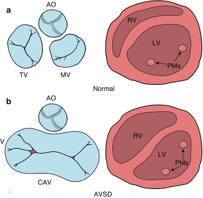
Fig. 8.2
Diagrammatic representation of the atrioventricular (AV) junction (on the left in blue) and the papillary muscles within the ventricle (on the right in pink), as seen from a caudal view. The normal heart is shown in panel a and an atrioventricular septal defect (AVSD) is shown in panel b. In contrast to the normal heart, in an AVSD the aortic valve is sprung anteriorly and superiorly (panel b, left); the papillary muscles are closely spaced and rotated (panel b, right). AO aortic valve, CAV common atrioventricular valve, LV left ventricle, MV mitral valve, PMs papillary muscles, RV right ventricle, TV tricuspid valve. Modifed from Silverman NH, The Secundum Atrial Septal Defect and Atrioventricular Septal Defects. In: Freedom R and Braunwald E, Atlas of Heart Diseases. St. Louis, Current Medicine LLC, 1996, with permission from Springer
The Rastelli classification of complete AVSDs, based on the morphology of the superior bridging leaflet, degree of bridging, and its chordal attachments, was originally considered to have prognostic implications. Although now less important surgically, this scheme is still widely used (Fig. 8.3) [9]. In our previously published experience of Rastelli type A AVSD, which accounted for 89 % of the complete form of AVSD, the superior bridging leaflet attaches to the ventricular septum. In that report Down syndrome was present in 58 % of the patients with this type of lesion but not with the other complete forms of AVSD [10]. In Rastelli type B, which accounted for 2 % of cases, the superior bridging leaflet attaches to a septal papillary muscle on the right side of the ventricular septum. However, it is often difficult to differentiate between the Rastelli types A and B. In Rastelli type C, which accounted for 9 %, the least developed or most primitive form of AVSD, the superior bridging leaflet extends to the anterior papillary muscle within the right ventricle. In this arrangement there are no chordal attachments to the septum and the freestanding right ventricular papillary muscle supports the right component of the superior bridging leaflet [11].
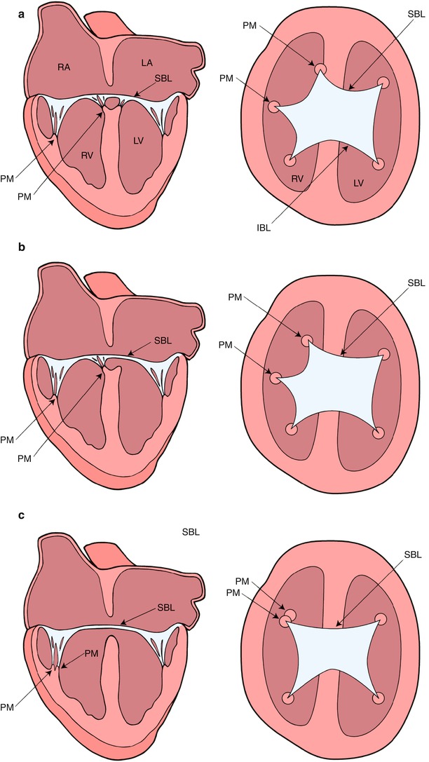
Fig. 8.3
Diagrammatic representation of the Rastelli classification of atrioventricular septal defects as assessed by transesophageal echocardiography in the mid esophageal four chamber (on the left) and deep transgastric sagittal views (on the right). In type A (panel a), the superior bridging leaflet attaches to the crest of the interventricular septum. In type B (panel b), the superior bridging leaflet attaches to a septal papillary muscle on the right aspect of the ventricular septum. In type C (panel c), the superior bridging leaflet is large and undivided. It extends to the anterior papillary muscle within the right ventricle. IBL inferior bridging leaflet, LA left atrium, LV left ventricle, PM papillary muscle, RA right atrium, RV right ventricle, SBL superior bridging leaflet. Modifed from Silverman NH, The Secundum Atrial Septal Defect and Atrioventricular Septal Defects. In: Freedom R and Braunwald E, Atlas of Heart Diseases. St. Louis, Current Medicine LLC, 1996, with permission from Springer
A number of other morphologic characteristics are present in AVSD. The positions of the left ventricular papillary muscles are rotated counter-clockwise (when viewed from the apex) due to counter-clockwise rotation of the LAVV commissures. The anterolateral papillary muscle is situated more medially at ‘three o’clock’, and the posteromedial papillary muscle is situated more laterally at ‘five o’clock’, compared with their normal positions at ‘four o’clock’ and ‘seven o’clock’, respectively as viewed from the parasternal left ventricular short axis view by TTE (Fig. 8.2) [10]. Papillary muscle rotation and approximation may cause a functionally parachute LAVV. Therefore, recognition of both papillary muscles within the left ventricle is important because repair of the LAVV may create an acquired parachute mitral valve deformity. In the normal heart the aortic valve is wedged between the mitral and tricuspid valves. In contrast, in AVSD, the aorta is “sprung” anteriorly and superiorly due to the lack of two separate AV orifices between which the aortic valve is normally situated (Fig. 8.2) [12]. These morphologic features, along with a discrepancy in the length of the left ventricular inlet and outlet (Fig. 8.4), create elongation and narrowing of the left ventricular outflow tract (LVOT), producing the so-called ‘goose–neck’ deformity characteristic of AVSDs initially described by its angiographic appearance.
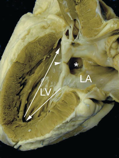
Fig. 8.4
Specimen of an ostium primum atrial septal defect demonstrating length disproportion between the inlet (arrow pointing down) and the outlet portions of the left ventricle (LV) from the apex (arrow pointing up). The asterisk is seen within the ostium primum atrial defect and the ventricular margins of this defect are the so-called ‘cleft’ (arrowhead) representing the fused origin of the superior and inferior bridging leaflets. LA left atrium
Shunting of blood in AVSD depends upon the attachment of the AV valve(s) to the septum and the direction of regurgitant valve jets. In diastole shunting is largely atrial, whereas in systole it is largely between the ventricles. If the valve leaflets adhere to the crest of the ventricular septum, as they do in ostium primum ASD, then the shunting is interatrial, whereas if the leaflets adhere to the interatrial septum as they do in isolated VSDs, the shunting is interventricular (Fig. 8.5). A left ventricular to right atrial shunt can be present, and less frequently in some cases, depending on the hemodynamics, right ventricular to left atrial shunts can be seen. These shunts are compounded by additional left ventricular to left atrial and right ventricular to right atrial regurgitant jets.
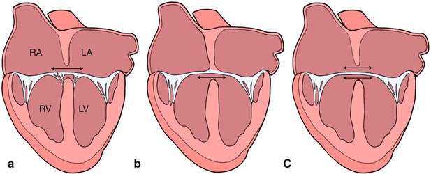
Fig. 8.5
Graphics depict atrial level shunting through an ostium primum atrial septal defect in panel a, ventricular level shunting in panel b, and combined atrial and ventricular shunting in panel c. Refer to text for details. LA left atrium, LV left ventricle, RA right atrium, RV right ventricle. Modifed from Silverman NH, The Secundum Atrial Septal Defect and Atrioventricular Septal Defects. In: Freedom R and Braunwald E, Atlas of Heart Diseases. St. Louis, Current Medicine LLC, 1996, with permission from Springer
In most cases, atrial level shunting is holodiastolic in nature and occurs in the left-to-right direction, however, flow reversal (e.g., right-to-left shunting) may occur briefly during the cardiac cycle related to associated pathology and hemodynamic status. The magnitude of shunting at the ventricular level is primarily determined by the size of the defect and the pulmonary vascular resistance. In regards to flow direction, left-to-right ventricular level shunting typically occurs during systole and is enhanced by a low pulmonary vascular resistance. Bidirectional shunting with right-to-left shunting in diastole, or predominant right-to-left shunting are seen in the setting of increased pulmonary vascular tone. Right ventricular to left atrial shunting in systole, although uncommonly seen, may contribute to arterial desaturation.
Pathophysiology
AVSDs represent a group of lesions that result in a volume load to the heart. The presence of an intracardiac communication(s) in these defects typically leads to left-to-right shunting and increased pulmonary blood flow. The concomitant presence of AV valve regurgitation further exacerbates the ventricular volume overload. In the case of complete defects, the symptomatology is magnified due to shunts both at atrial and ventricular levels, frequent ventriculo-atrial shunts, and the presence of pulmonary hypertension. The elevated pulmonary artery pressure also imposes a pressure load on the right ventricle. Due to these factors, patients with complete AVSDs are generally in significant congestive heart failure; these symptoms account for the fact that complete AVSDs require corrective surgery during infancy. In some cases, elevated pulmonary vascular resistance limits left-to-right shunting and in fact, as mentioned, may even lead to predominant right-to-left shunting resulting in cyanosis. In the case of partial defects with a VSD, interventricular pressure restriction across the small defect limits the degree of ventricular left-to-right shunting, thereby minimizing pulmonary overcirculation and volume overload. Nonetheless these patients can still present with congestive symptoms if there is hemodynamically significant LAVV regurgitation. In partial defects without significant LAVV regurgitation, the physiology mimics that of any other atrial level communication, and clinical symptoms might be minimal or absent. In this case, left-to-right atrial level shunting is determined by the relative compliances of the ventricular chambers.
Management Considerations
A number of surgical techniques have been applied to the surgical correction of AVSDs. In complete defects, the goal of the intervention is reconstruction of the common AV valve to achieve two separate and competent AV valves, along with closure of the LAVV cleft, closure of the intracardiac communications, and repair of associated defects. This can be accomplished by a variety of approaches (i.e., single patch, double-patch, and modified techniques) [13–15]. The objectives of the surgical repair in partial AVSDs are to eliminate shunting, in the majority of cases by patch closure of the primum septal defect, and closure of the cleft to create the equivalent of an anterior mitral valve leaflet that coapts well with the posterior leaflet without significant regurgitation or stenosis.
Transesophageal Echocardiography
Preoperative TEE Evaluation
The most common indication for TEE in patients with CHD is for assessment during cardiac surgery [16]. Intraoperative TEE has improved surgical outcomes by providing the surgeon with real-time information about cardiac anatomy and valvular function [3, 17]. TEE can confirm or exclude preoperative transthoracic information and assess the immediate preoperative hemodynamics and ventricular function. In addition, important findings and key anatomic and hemodynamic features can be directly demonstrated to the perioperative providers for immediate review just prior to commencement of the operation. Preoperative TEE may also facilitate the placement of central venous catheters, selection of anesthetic agents, and use of preoperative inotropic support by demonstrating ventricular systolic function and size (refer to Chaps. 3 and 15) [18, 19]. However, in keeping with the recommendations of the Task Force of the Pediatric Council of the American Society of Echocardiography on pediatric TEE, as in the case of all congenital cardiac defects, an AVSD and its anatomical features should be defined completely preoperatively by transthoracic imaging [16]. The prebypass TEE should then confirm the TTE findings. Pertinent points to be addressed by the prebypass TEE include:
The atrial communication(s)
The type and extent of the ventricular communication(s)
Atrioventricular valve morphology and function
Shunting patterns and AV valve regurgitation
Commitment of the AV junction to the underlying ventricular mass and the size of the ventricles (balance)
Associated cardiac anomalies, including patent ductus arteriosus, left superior vena cava to coronary sinus, and coexistent lesions of moderate complexity such as tetralogy of Fallot
In addition, on the prebypass TEE, the operator should search for additional VSDs that might require surgical intervention as these may be easily missed in previous TTE imaging. The echocardiographer should also document the degree of AV valve regurgitation to facilitate comparison with any residual regurgitation after repair.
Intraoperative Imaging
Two-Dimensional Imaging of Complete Defects
As previously mentioned, the preoperative examination should focus on the details of the anatomy, functional assessment of the AV valves(s), and evaluation of associated defects as follows:
The Atrioventricular Septum and Common Atrioventricular Valve
The AV septum is best imaged from the mid esophageal four chamber (ME 4 Ch) view in the axial orientation. Further inferior or superior probe positioning within the mid esophagus, as well as anteflexion/retroflexion, allows optimization of the view and visualization of additional structures such as the LVOT. The ME 4 Ch demonstrates the relationship of the AV valves to each other and to the septa. In this defect, the AV valves insert onto the interventricular septum at the same level (Fig. 8.6, Video 8.1). Septal attachments of the chordae tendineae and papillary muscle apparatus of the LAVV define the ‘cleft’ or commissure between the superior and inferior bridging leaflets. The echocardiographer should assess the anatomical boundaries of the atrial and septal components of the defect. Scanning posteriorly (probe retroflexion) from the ME 4 Ch view defines the posterior limits of the atrial and ventricular components of the septal defect. Locating the crux of the heart (coronary sinus) with retroflexion of the transducer followed by slight anteflexion defines the position of the inferior components of the AV valve as it crosses the septum. The superior component is correspondingly defined in this plane by anteflexing the probe so that the bridging leaflet is observed crossing the anterior aspect of the defect. Anterior angulation of the transducer by cephalad retraction of the probe and further anteflexion from the ME 4 Ch view to a ‘five chamber view’ defines the anterior extent of the septal defects, the relationship of the chordae tendineae to the underlying ventricular septum and the LVOT, and the aortic root.
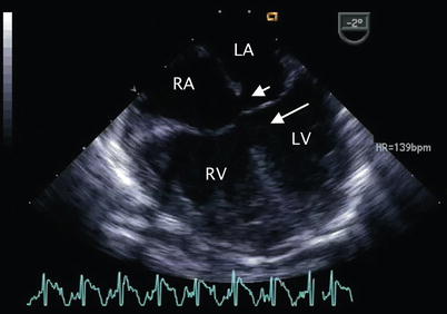
Fig. 8.6
Mid esophageal four chamber view demonstrating a complete atrioventricular septal defect. The primum atrial septal defect (short arrow) and inlet ventricular septal defect (long arrow) that characterize this malformation are shown. LA left atrium, LV left ventricle, RA right atrium, RV right ventricle
The morphology of the common AV valve and chordal attachments should be assessed in multiple planes including those displayed by the ME 4 Ch, mid esophageal long axis (ME LAX), TG basal short axis (TG Basal SAX), transgastric two chamber (TG 2 Ch), deep transgastric long axis (DTG LAX), and deep transgastric sagittal (DTG Sagittal) views. The ME 4 Ch view is particularly useful for defining the Rastelli type, although the operator must be cognizant of the scan plane passing through the superior leaflet (Fig. 8.3). This is achieved by pulling the transducer cephalad from this view into the upper esophagus, applying anteflexion and then directing the scan plane slightly posterior by advancing the transducer to the level of the mid esophagus until the superior bridging leaflet is identified. Transgastric and deep transgastric short axis views of the ventricles that display the common AV valve en face, much like a transthoracic subcostal view, also assist in the determination of Rastelli type as well as degree of balance of the AV valve over the ventricles, and attachments of the valve to the left and right ventricular papillary muscles (Figs. 8.3 and 8.7, Video 8.2). Because the plane of the AV junction is oriented more vertically in patients with an AVSD, the true short axis view in this anomaly is obtained using a more sagittal plane, which may require further angulation of the probe, by rotation and anteflexion [10, 20]. It is usually helpful to advance the probe into the stomach, apply anteflexion and then further advance the probe while it is flexed to increase its anterior curvature. The probe may then be gently withdrawn while maintaining anteflexion towards the esophago-gastric junction, until the optimal image comes into view. This “in between” deep transgastric view with multiplane angle between 0° (DTG LAX view) and 90° (DTG Sagittal view) is optimal to display the common AV valve en face (Fig. 8.8, Video 8.3).
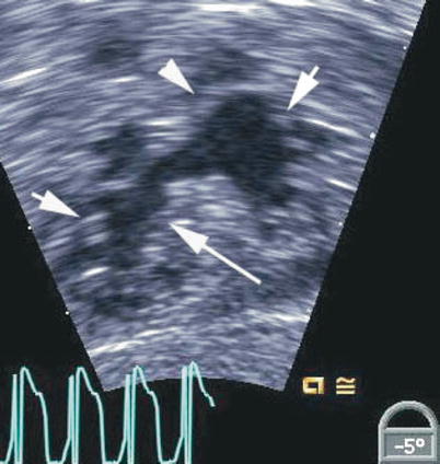
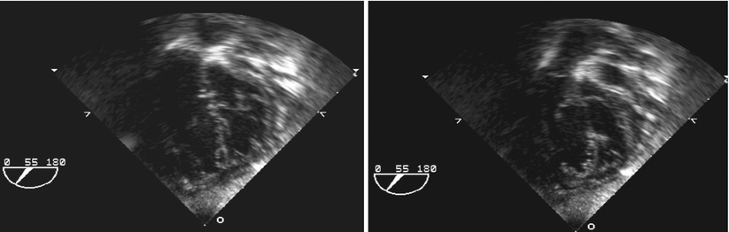
Fig. 8.7
Deep transgastric view showing the open common atrioventricular valve en face. The valve morphology is well seen in this view including the superior bridging leaflet (arrowhead), inferior bridging leaflet (long arrow) and the right and left mural leaflets (short arrows)
Fig. 8.8
Deep transgastric views at 55° display common atrioventricular valve en face in infant with complete atrioventricular septal defect. Left panel depicts closed valve in systolic frame and right panel opened valve in diastolic frame
There is considerable morphologic and functional variation in the AV valves and their support apparatus. Short axis scanning of the entire AV orifice from a transgastric or deep transgastric plane displays the five leaflets of the common AV valve and the cleft between the left-sided components of the bridging leaflets (Fig. 8.7, Video 8.2). In AVSD, the cleft always points toward the inlet septum (Figs. 8.9 and 8.10, Videos 8.4 and 8.5), while an isolated cleft that is not part of an AVSD points to the LVOT [20–22]. The morphology of the left component of the AV valve should also be examined by imaging in the ME LAX view with the transducer plane at approximately 1200 (Fig. 8.11, Video 8.6). The left component of the AV valve may also exhibit a double orifice, which can be identified in the en face view (Fig. 8.12, Video 8.7) [23, 24].
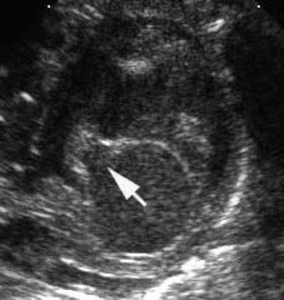
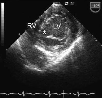
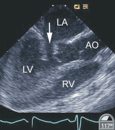
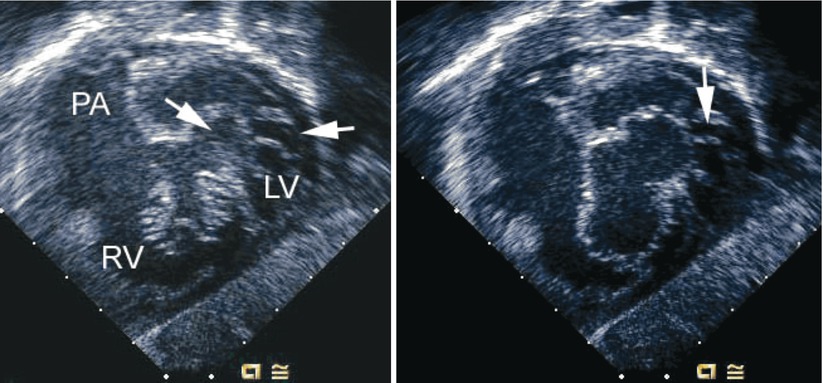
Fig. 8.9
Transthoracic parasternal short axis image demonstrating a cleft in left atrioventricular valve (arrow) pointing toward the inlet septum in an atrioventricular septal defect
Fig. 8.10
Transgastric basal short axis view displaying cleft in the left atrioventricular valve (asterisk) in a patient with an atrioventricular septal defect. LV left ventricle, RV right ventricle
Fig. 8.11
Mid esophageal long axis view displaying a cleft in the left-sided component of a common atrioventricular valve (arrow). This is associated with abnormal motion of this region of the valve as shown. In this defect the cleft points towards the septum. AO aorta, LA left atrium, LV left ventricle, RV right ventricle
Fig. 8.12
Left panel, deep transgastric sagittal transesophageal echocardiographic image of a child with an atrioventricular septal defect and double-orifice of the left component of the atrioventricular valve. The left component is marked by the arrows during systole. Right panel, corresponding diastolic frame demonstrating the common atrioventricular valve orifice en face with its right and left components. An arrow notes the area of double orifice. LV left ventricle, PA pulmonary artery, RV right ventricle
The Interatrial Communication
An ostium primum type atrial septal communication is found in most AVSDs. In a study examining the cross-sectional echocardiographic findings in AVSDs, a primum ASD was identified in nearly all patients (170 out of 171) [10]. Among the entire cohort, 74 % had a complete AVSD and 25 % a partial defect. A single patient had only a VSD component and cleft mitral valve.
The ostium primum ASD can be defined from a number of views, but is best outlined when the atrial septum is perpendicular to the transducer. This can be accomplished in the ME 4 Ch view (approximately 00) by rotating the shaft of the transducer slightly clockwise to focus on the interatrial septum (Fig. 8.13, Video 8.8). The size of the ostium primum defect may vary from very large to extremely small. When the interatrial septum is well formed, it can be defined in the ME 4 Ch view as extending from the interatrial groove down to the lower edge of the inferior rim of the oval fossa. The ostium primum defect extends from the lower edge of the true atrial septum to the conjoined AV valve bridging leaflets inferiorly [10].The junction of the lower end of the atrial septum and an enlarged coronary sinus due to the connection of a left superior vena cava should not be confused with an ostium primum defect, particularly because the two structures are adjacent to each other. The coronary sinus is situated just anterior to the crux of the heart, and an ostium primum defect is located anterior to the coronary sinus. The ostium primum defect can also be identified from the mid esophageal bicaval (ME Bicaval) view with the plane at approximately 900. Shunting across the ostium primum defect occurs during diastole and in most cases flow is laminar and low velocity. Aliasing and higher than expected flow velocities can be seen depending on the size of the defect and relative amount of blood flow across it.
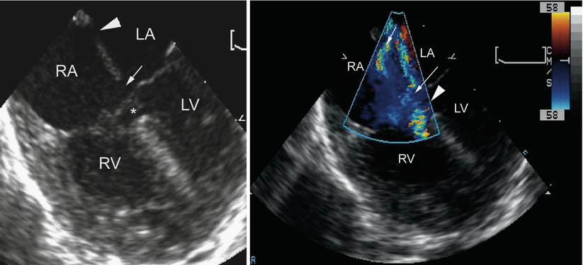
Fig. 8.13
Left panel, mid esophageal four chamber view depicting an atrioventricular septal defect. There is dual atrial level shunting at both the level of the ostium primum (arrow) and ostium secundum defect (arrowhead). The asterisk within the ventricular mass shows the ventricular septal defect surrounded by aneurysmal tissue, or so-called ‘tricuspid pouch’. Right panel, the color flow information is superimposed upon the morphologic image showing the left-to-right atrial shunting across both atrial communications (arrows). The accelerative flow in the region of the tricuspid pouch (arrowhead) indicates the presence of a small ventricular septal defect. LA left atrium, LV left ventricle, RA right atrium, RV right ventricle
Ostium secundum ASDs are also frequently present (Figs. 8.13 and 8.14, Videos 8.8 and 8.9). In isomerism of the atrial appendages, the atrial septum can be almost completely absent with only a strand of atrial tissue remaining.
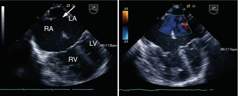
Fig. 8.14
Left panel, a large secundum atrial septal defect is seen (arrow) in association with an atrioventricular septal defect. Right panel, color interrogation demonstrates atrial level left-to-right shunting (blue flow). LA left atrium, LV left ventricle, RA right atrium, RV right ventricle
The Ventricular Component of the Defect
The ventricular component of the AVSD is displayed best in the ME 4 Ch view where its central portion below the bridging AV leaflets is seen (Fig. 8.15, Video 8.10). Other planes such as the ME LAX, TG Basal SAX, transgastric mid short axis (TG Mid SAX) and the deep transgastric views should also be used (Fig. 8.16, Video 8.11) to assess the ventricular communication(s). Isolated ventricular defects are rare (1 out of 171 patients with AVSDs in series described previously) and have been classified as ‘VSDs of the AV canal type’ (Fig. 8.17, Video 8.12). These differ from true isolated VSDs in the inlet septum (discussed in Chap. 9) in that they are located more posteriorly and have typical associations such as rotated papillary muscles and a cleft in the left component of the AV valve [25]. They can also have chordae from the left AV valve attaching to the crest of the ventricular septum.
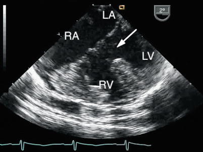
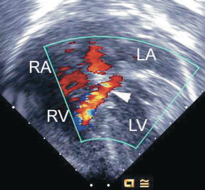
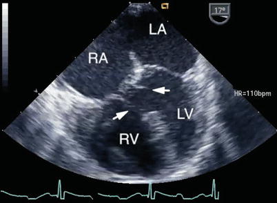
Fig. 8.15
The large ventricular component of a complete atrioventricular septal defect is shown (arrow). The right ventricular hypertrophy reflects the elevated pulmonary artery pressure that characterizes the lesion. LA left atrium, LV left ventricle, RA right atrium, RV right ventricle
Fig. 8.16
Deep transgastric image obtained as a four chamber equivalent view showing a shunt jet (arrowhead) originating within the left ventricle (LV) associated with a flow convergence signal before it passes through the ventricular component of an atrioventricular septal defect into the right ventricle (RV). LA left atrium, RA right atrium
Fig. 8.17
Mid esophageal four chamber view depicting a ventricular septal defect of the ‘atrioventricular canal-type’. In this defect separate atrioventricular valve orifices were present and the atrial communication was of the secundum-type. Several chordal attachments (arrows) are seen from the atrioventricular valves to the crest of the ventricular septum. Note the lack of normal offsetting of the atrioventricular valves. LA left atrium, LV left ventricle, RA right atrium, RV right ventricle
The proximity of the VSD to the AV valves and their chordal apparatus may obscure the defect in diastole. Therefore, the ventricular component of the defect is best defined during systole when the AV valve leaflets are closed and the chordal apparatus tensed. During systole, the valve leaflets move away from the ventricular component of the defect exposing the VSD and its relationship to the underlying papillary muscles and/or the ventricular septum. In those situations when the defect is not easily visualized because of dense chordal attachments to the crest of the interventricular septum, flow may still be detected by Doppler color flow imaging (Fig. 8.13, Video 8.8). The atrial component of the defect can be difficult to define when the common AV valve is open, especially if small, as there is complete communication between the atria and ventricles. This may be better appreciated when the valve is closed. Thus, definition of the components of the defect should be performed during the full cardiac cycle.
AVSDs intrinsically have elongation of the LVOT and shortening of the left ventricular inflow, creating inlet–outlet disproportion (Fig. 8.4) as mentioned. This is in contrast to the left ventricle in the normal heart where the inlet and outlet are of equal length. Anterior angulation of the transducer from the deep transgastric window and a multiplane angle of 900 to visualize the aortic root (DTG Sagittal view) demonstrates the ‘gooseneck deformity’ of the LVOT (Fig. 8.18, Video 8.13) [10]. The outflow tract can also be imaged from the ME LAX and ME 4 Ch view with anteflexion of the imaging probe. Chordal attachments of the AV valve leaflets, and in some instances accessory left AV valve tissue can also contribute to LVOT obstruction (Fig. 8.19, Video 8.14).
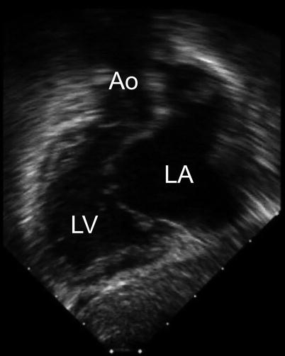
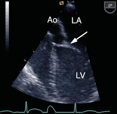
Fig. 8.18
The ‘goose neck’ deformity of the left ventricular outflow tract that characterizes an atrioventricular septal defect is shown in this deep transgastric sagittal view. Ao aorta, LA left atrium, LV left ventricle
Fig. 8.19
Modified mid esophageal four chamber view with anterior transducer angulation displaying chordal attachments of the left atrioventricular valve across the left ventricular outflow tract onto the interventricular septum (arrow). This can result in outflow tract obstruction. Ao aorta, LA left atrium, LV left ventricle
Commitment of the Atrioventricular Junction to the Ventricles
Usually the right and left portions of the AV junction are equally committed to their respective ventricles, however, preferential commitment to either ventricle can occur in approximately 5–10 % of cases, resulting in left, or more commonly right ventricular dominance (Fig. 8.20) [10, 26]. This is also known as an unbalanced AVSD.
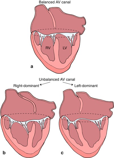
Fig. 8.20
This diagram depicts a ‘balanced’ atrioventricular septal defect in panel a where the atrioventricular valve lies equally above the ventricular mass. In panel b, the atrioventricular valve is committed preferentially to the right ventricle (RV) resulting in a ‘right dominant’ atrioventricular septal defect and a hypoplastic left ventricle (LV). Panel c depicts a ‘left dominant’ atrioventricular septal defect, where the atrioventricular valve is committed preferentially to the left ventricle. Modifed from Silverman NH, The Secundum Atrial Septal Defect and Atrioventricular Septal Defects. In: Freedom R and Braunwald E, Atlas of Heart Diseases. St. Louis, Current Medicine LLC, 1996, with permission from Springer.
The commitment of the AV orifice to the underlying ventricles by TEE can be defined from the ME 4 Ch view (Fig. 8.21, Video 8.15), but additional views (including the TG Basal SAX and deep transgastric views) provide further comprehensive assessment. Unbalance of AV tissue over the ventricles, ventricular hypoplasia or the presence of a single left ventricular papillary muscle may preclude a biventricular repair. Unbalanced AVSDs are commonly associated with heterotaxy syndromes, particularly right atrial isomerism (asplenia). This is further discussed in Chap. 10.
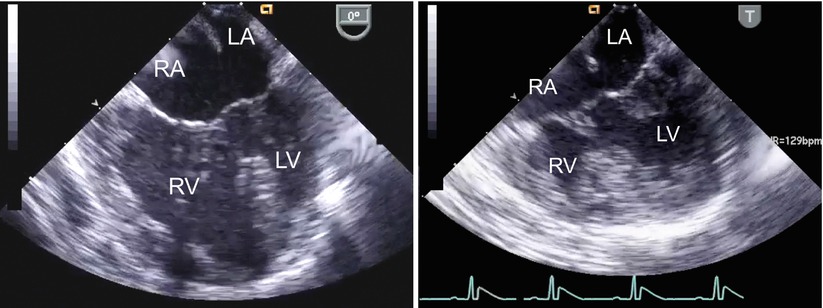
Fig. 8.21
The figure displays unbalanced atrioventricular septal defects in the mid esophageal four chamber view (left panel, right dominant defect; right panel, left dominant defect). LA left atrium; LV left ventricle; RA right atrium; RV right ventricle
As this represents an important issue for surgical planning, echocardiographic criteria have been investigated to determine the extent of unbalance in order to discriminate between balanced and unbalanced forms of the defect. This is particularly relevant to settings where the degree of unbalance is not extreme, being readily determined by qualitative assessment. A parameter studied by TTE has been referred to as ‘atrioventricular valve index’ (AVVI) [27].This is obtained from a subcostal left anterior oblique cross section (en face view), where the relationship between the common AV valve and ventricular septum are visualized. The orifice of the common AV valve is traced in diastole and after a line in drawn corresponding to the plane of the interventricular septum, the respective areas of the left and right components are determined. In its initial description, the AVVI was expressed as the ratio of the area of the smaller AV valve component to the larger component. Most recently, a modified AVVI has been used to correlate anatomic type of AVSD and surgical decision-making [28]. For this purpose the index was simplified, being derived by dividing the LAVV area by the total AV valve area. An AVVI of <0.4 was considered to define right dominance and >0.6, left dominance. Although, not formally studied by transesophageal imaging, this index can also be derived from deep transgastric interrogation using the equivalent en face view, allowing for evaluation of balance versus unbalance at the time of surgical intervention.
Two-Dimensional Imaging of Incomplete (Partial) Defects
As indicated, in all forms of AVSD the AV junction consists of a single annulus, but there may be a single valve orifice (the complete form), or two separate orifices (the partial form), formed by a tongue of tissue connecting the two bridging leaflets and dividing the common orifice. Functionally separated AV orifices also occur when only an atrial or ventricular component of the defect is present. An isolated ventricular component of an AVSD occurs only rarely, as previously noted. An isolated atrial component (ostium primum ASD) occurs much more frequently and results from fusion of the bridging leaflets with the ventricular septum. A cleft in the mitral valve, best seen in views that display the valve in its short axis, can be associated with variable degrees of regurgitation.
Partial AVSDs may exhibit redundant tissue prolapsing through the interventricular communication into the right ventricle, also known as tricuspid pouch. This is comprised by connecting tissue between the bridging leaflets and tissue from the superior bridging leaflet and its tensor apparatus [10, 29]. This structure can be seen in the ME 4 Ch view (Fig. 8.22, Video 8.16) and short axis images of the common AV valve from the transgastric and deep transgastric windows, and has an identical appearance to that of tricuspid tissue tags or membranous ventricular septum aneurysm found with perimembranous VSDs. The size of the tricuspid pouch can be quite prominent.
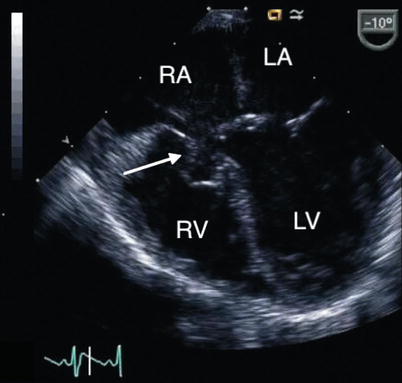
Fig. 8.22
Mid esophageal four chamber view displays a tricuspid pouch lesion (arrow) in a patient with a partial atrioventricular septal defect. LA left atrium, LV left ventricle, RA right atrium, RV right ventricle
Doppler Evaluation of Defects
The detection of shunting patterns by color flow Doppler is important for the surgical repair as well for prognosis [10, 30, 31]. This applies to both the evaluation of intracardiac communications and valve regurgitation. Color flow mapping facilitates the assessment of intracardiac shunting (Figs. 8.14, 8.16, and 8.23, Videos 8.9 and 8.11) and is particularly helpful in the assessment of flow when there is limited potential for interventricular shunting under the superior bridging leaflet (restrictive VSD) in the setting of a partial AVSD (Fig. 8.13, Video 8.8). The peak velocity of the jet across the ventricular level shunt, as obtained from spectral Doppler interrogation, represents the pressure gradient between the ventricles in the absence of right ventricular outflow tract obstruction (RVOTO). This can be used to estimate right ventricular and pulmonary artery pressures by applying the simplified Bernoulli equation as follows:
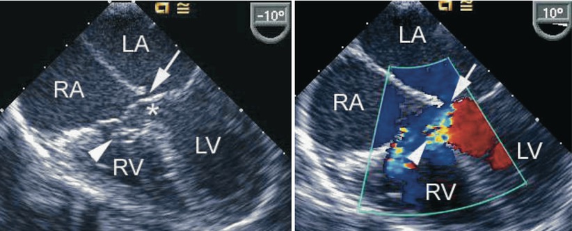
Fig. 8.23
The figure demonstrates an atrioventricular septal defect in a two-dimensional mid esophageal four chamber view in the left panel and corresponding color flow mapping demonstrating left-to-right shunting in the right panel. The arrow points to a small primum atrial septal defect. The arrowhead points to a tricuspid pouch and the asterisk indicates the ventricular septal defect. LA left atrium, LV left ventricle, RA right atrium, RV right ventricle
Right Ventricular Systolic Pressure = Systemic Systolic Pressure—Peak Gradient Across Ventricles
Peak Gradient Across Ventricles = 4 (Peak VSD Velocity)2
Valves with similar morphology can display quite different degrees of regurgitation and functional impairment. Color Doppler interrogation requires an assessment in multiple views of all defects (Fig. 8.24, Video 8.17). Particularly in patients with a partial form of AVSD, the site where regurgitation occurs is important for surgical repair. AV valve regurgitation through the left-sided cleft is frequently directed centrally and may be part of a left ventricular to right atrial shunt. (Fig. 8.25, Video 8.18) The jet may also be directed leftwards and becomes a left ventricular to left atrial shunt. This may be related to mural leaflet hypoplasia of the left component of the AV valve [30]. Right ventricular to right atrial regurgitation may also be substantial (Fig. 8.26, Video 8.19). Often, multiple jets are present (Figs. 8.25 and 8.26, Videos 8.18 and 8.19).
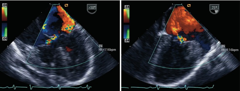
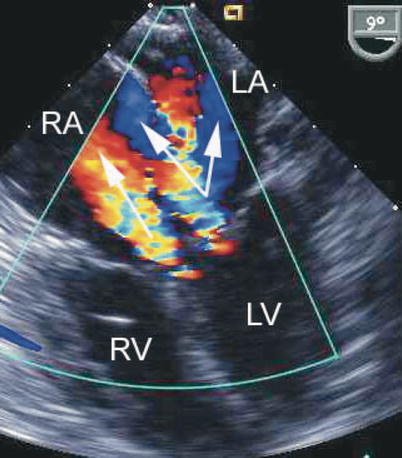
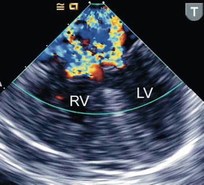
Fig. 8.24
The figure displays a complete atrioventricular septal defect in different transesophageal echocardiographic cross-sections. Color flow mapping demonstrates intracardiac shunting in addition to a significant regurgitant jet across the left component of the common atrioventricular valve. The characteristics of the regurgitant jet are further defined by multiplane imaging, highlighting the importance of color Doppler interrogation in multiple views
Fig. 8.25
Preoperative mid esophageal four chamber view displaying an atrioventricular septal defect. Color flow mapping depicts multiple regurgitant jets. The arrows point to regurgitation from the left ventricle (LV) into both the left atrium (LA) and right atrium (RA), split by the atrial septum, as well as a separate jet from the left-sided component of the atrioventricular septal defect directed into the RA (left ventricular to right atrial shunt). RV right ventricle
Fig. 8.26
The image shows preoperative color flow information obtained in a mid esophageal four chamber view using a pediatric biplane transesophageal probe in a small infant with a complete atrioventricular septal defect. Significant regurgitation is depicted from both the left and right atrioventricular valvar components, during systole. LV left ventricle, RV right ventricle
Precise definition of the regurgitant jet is important for accurate interpretation of a pressure gradient in patients with partial defects. A left ventricular to right atrial regurgitant velocity will yield a high estimated gradient due to the large pressure difference between the two chambers, and if this is misinterpreted as a tricuspid regurgitant velocity, the true right ventricular pressure could mistakenly be overestimated. If, under the circumstances described here, an accurate right ventricular to right atrial jet can be identified and interrogated by spectral Doppler, a much lower velocity might be recorded.
Associated Cardiac Lesions
Additional muscular VSDs can be found in 10 % of patients with AVSDs [10]. Color Doppler flow mapping facilitates demonstration of these defects but when pulmonary hypertension is present these lesions may be missed. Decreasing the color flow Doppler scale can increase the sensitivity for low velocity color flow signals and sometimes uncover associated muscular VSDs. Tetralogy of Fallot is an important conotruncal malformation that can be seen in combination with an AVSD. This lesion is colloquially referred to as a ‘tet-canal’ defect. In this setting, the Rastelli type C defect is most commonly found (Fig. 8.27, Video 8.20). Down syndrome is present in the majority of these patients. The echocardiographic findings in this lesion are those previously mentioned for AVSDs, in addition to the features that characterize tetralogy as discussed in Chap. 12 (i.e., RVOT obstruction, aortic override). Other lesions less frequently encountered include valvar pulmonary stenosis, double outlet right ventricle, transposition of the great arteries, and truncus arteriosus. Subaortic stenosis may contribute to LVOTO and may be associated with aortic coarctation [32]. Patent ductus arteriosus is also common, particularly in patients with Down syndrome. Other chromosomal and genetic abnormalities can also be associated with AVSDs [33]. A high percentage of heterotaxy patients will have AVSDs (refer to Chap. 10). In this setting, double outlet right ventricle is a common association. The comprehensive preoperative TEE evaluation in the patient with an AVSD should also include an assessment of associated lesions as described throughout this textbook for each of the respective defects.
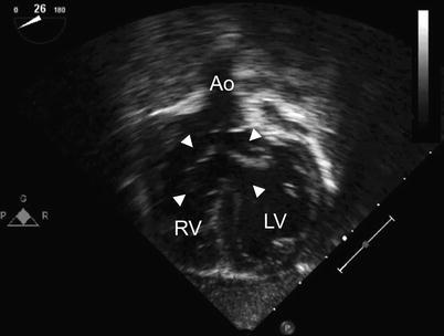
Fig. 8.27
Deep transgastric long axis view in infant with Down syndrome and ‘tet-canal defect’. Note the relationship of the aorta (Ao) to the common atrioventricular valve (arrowheads). The characteristic aortic override in tetralogy of Fallot is well seen. LV left ventricle, RV right ventricle
Postoperative TEE Evaluation
The most important goal of the postbypass TEE study is to identify significant hemodynamic abnormalities that should be addressed at the time of surgery. Important lesions requiring revision/reintervention include: residual LAVV valve regurgitation or stenosis, residual or additional VSDs, and LVOT obstruction (LVOTO) [34]. These problems, along with the need for permanent pacemaker insertion/revision, are the major indications for reoperation in patients with AVSDs, and a major cause of morbidity and mortality.
TEE has been shown to identify and estimate the severity of valvar regurgitation [35, 36].This imaging modality has been used to accurately localize mitral regurgitant lesions in adults and found to improve the assessment of patients with significant mitral regurgitation [37, 38]. Likewise, intraoperative TEE is also used to assess LAVV function after surgery in children with AVSDs (Fig. 8.28, Video 8.21) [39, 40]. Severe LAVV regurgitation was found by TEE post AVSD surgery in 5 % of patients in one study [17]. Further repair was undertaken so that no patient left the operating room with severe regurgitation. It is of interest that this study found a discrepancy in the degree of mitral regurgitation identified by intraoperative TEE versus predischarge TTE in 45 % of patients. In most cases (81 %), the degree of mitral regurgitation on the predischarge TTE was worse than that found by TEE in the operating room. This may be due to lower systemic blood pressures and higher heart rates at the time of surgery, underestimating the true severity of AV valve regurgitation. It was concluded that the grade of mitral regurgitation by intraoperative TEE does not predict the severity of regurgitation at follow-up as imaged by TTE and it was suggested that TEE findings should be interpreted in the light of the hemodynamic status. Others have also found discrepancies in the severity of mitral valve regurgitation by intraoperative TEE and subsequent TTE [41, 42]. However, these discrepancies were generally not large enough to necessitate reoperation in early to mid-term follow up, leading the authors to conclude that intraoperative TEE may be used as a tool to predict durability of surgical results and to decrease the incidence of reoperation in complete AVSDs. In other studies, an excellent correlation has been identified between intraoperative color flow assessment of LAVV regurgitation and immediate postoperative evaluation [43]. The need for reoperation was found to correlate significantly with the severity of LAVV regurgitation (r = 0.68) and intraoperative imaging was found to accurately predict the development of early postoperative heart failure and subsequent reoperation for AVSD [43].
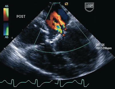
Fig. 8.28
Postoperative transesophageal echocardiogram following repair of a complete atrioventricular septal defect. Color Doppler interrogation demonstrates two small jets of left atrioventricular valve regurgitation. The jet closest to the interatrial septum represents regurgitation across a residual cleft
We believe that it may not be possible to reliably assess the real degree of regurgitation because of loading conditions as well as changes in myocardial contractility, blood pressure, systemic vascular resistance, and wear and tear as the repair settles into the postoperative functional status. One of the significant errors that can be made is a too rapid report to the surgeon that the regurgitation is minimal immediately after separation from cardiopulmonary bypass. Therefore the initial post-repair TEE assessment should be followed by a later evaluation made prior to removal of the imaging probe.
The difficulties in the echocardiographic assessment of mitral valve regurgitation in children after repair of AVSD were underscored in a recent study [44]. The cohort in this report included children enrolled in a multicenter drug study (enalapril) 6 months following repair of AVSD. The evaluation of the severity of mitral regurgitation by TTE was based in the following criteria: (1) qualitative assessment; (2) measurement of vena contracta width with respect to body size; (3) calculation of vena contracta area; and (4) determination of mitral regurgitant volume and fraction. Among the quantitative parameters evaluated, the methods used in the assessment of the vena contracta were found to be minimally superior to qualitative mitral regurgitation grading. Values for regurgitant volume and fraction were frequently negative. This, in addition to poor interobserver agreement in these parameters, limited their utility.
Stenosis of the left component of the AV valve occurs most commonly after closure of the cleft in the setting of a parachute valve, and in some cases, a double-orifice LAVV. Doppler interrogation during postbypass TEE imaging in the ME 4 Ch view should recognize obstruction to left ventricular inflow so that the surgeon can relieve some of the sutures closing the cleft, or adjust an annuloplasty, if this was undertaken. This assessment can also be performed in the mid esophageal two chamber (ME 2 Ch) and ME LAX views (Fig. 8.29, Video 8.22). In this situation, the best possible balance between hemodynamically tolerable LAVV stenosis and regurgitation needs to be achieved. In rare instances, implantation of a mitral prosthesis becomes necessary; however, this is problematic in smaller patients due to the small size of the LAVV annulus.
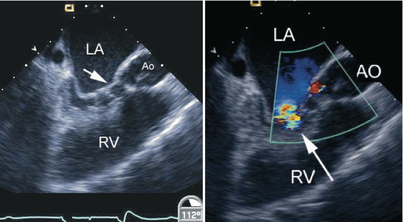
Fig. 8.29
Left panel, diastolic frame in a mid esophageal long axis view displaying mitral valve stenosis resulting from cleft closure (arrow) following repair of an atrioventricular septal defect. The left atrium (LA) appears dilated. Narrowing of the left ventricular outflow tract is also noted in association with multiple chordal attachments across the subaortic region onto the ventricular septum. Right panel, color flow information superimposed on the morphologic data shows a turbulent jet across the left ventricular inflow corresponding to mitral stenosis (arrow). The coronary sinus appears mildly dilated. Ao/AO aorta, RV right ventricle
An important aspect of the postoperative evaluation in AVSDs is interrogation for the presence of residual intracardiac shunts. Color Doppler is essential in this evaluation and when subsequent reoperation is required to address residual/recurrent hemodynamically significant shunts (Fig. 8.30, Video 8.23).
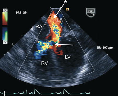
Fig. 8.30
Preoperative transesophageal echocardiogram in an infant requiring reoperation to address a residual inlet ventricular septal defect (arrow) as well as significant regurgitation across a large left atrioventricular valve cleft related to suture dehiscence (arrow with asterisk). Both lesions are well characterized by color flow imaging in the mid esophageal four chamber view. LA left atrium, LV left ventricle, RA right atrium, RV right ventricle
AVSDs, as previously stated, can be associated with LVOTO (Fig. 8.29, Video 8.22) [32]. Potential mechanisms of residual or new onset LVOTO include discrete subaortic fibrous stenosis, tunnel stenosis, accessory LAVV tissue and chordae, redundant LAVV tissue and apparatus, aneurysm of the mitral valve, abnormal papillary muscles, anteroseptal twist, malaligned aorta over the septum, hypertrophic muscle, and mitral valve prosthesis [45–47]. Although LVOTO usually becomes significant only in the period following surgery, the echocardiographer should investigate for LVOTO at the time of intraoperative TEE, especially in the postbypass evaluation (Fig. 8.31, Video 8.24), as any obstruction to flow may need to be addressed at time of surgery.
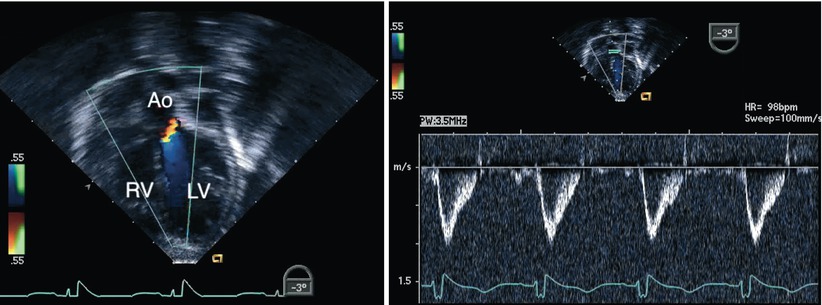
Fig. 8.31
Deep transgastric long axis view obtained following repair of an atrioventricular septal defect. The image displays interrogation of the left ventricular outflow tract using a combination of Doppler modalities (color flow mapping on the left panel and spectral Doppler on the right panel). No evidence of obstruction was demonstrated in this case. Note the favorable angle for pulsed wave Doppler interrogation of the outflow tract in this view. Ao aorta, LV left ventricle, RV right ventricle
TEE is also of significant benefit in the recognition of other less common but important complications resulting from the repair of these defects. These problems include unusual intracardiac shunts (Fig. 8.32, Video 8.25) and the rare instance when inferior vena caval flow may be inadvertently directed into the left atrium. The use of contrast echocardiography can be particularly useful in the evaluation of these issues (Fig. 8.33, Video 8.26).
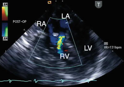
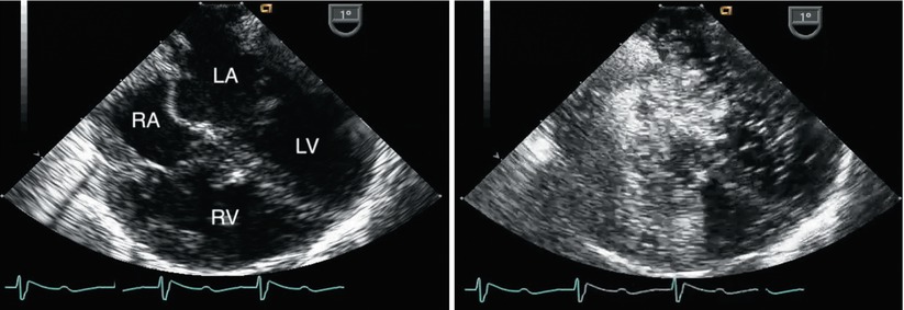
Fig. 8.32
Postbypass transesophageal echocardiogram obtained in the mid esophageal four chamber view demonstrates flow by color Doppler from the left atrium (LA) into the right ventricle (RV; blue jet). This communication, representing a left-to-right shunt, was inadvertently created during repair of the defect. The echocardiographic findings led to revision of the repair. LV left ventricle, RA right atrium
Fig. 8.33
Left panel, mid esophageal four chamber view obtained immediately after separation from bypass following repair of a complete atrioventricular septal defect. Both atrial and ventricular septal patches are seen. Right panel, contrast study performed to evaluate a small color Doppler signal suggestive of residual ventricular level shunting (not shown). Agitated saline injected through a femoral venous catheter demonstrated opacification of the right atrium with unexpected almost immediate appearance of contrast in the superior aspect of the left atrium. The concern for mistaken partial incorporation of inferior vena cava flow into the LA (right-to-left shunt) was raised. This was confirmed upon return to bypass. After revision of the repair a repeat contrast study demonstrated a normal flow pattern and no residual shunts. LA left atrium, LV left ventricle, RA right atrium, RV right ventricle
Three-Dimensional Echocardiographic Imaging
Three-dimensional (3D) TTE has been used to define the anatomy of the primum ASD in AVSDs and found to provide important information regarding the spatial orientation and alignment of the endocardial cushion region relative to the ventricles. The ability to determine this alignment and to predict the corresponding size and orientation of the AV valve has important clinical implications and would be essential for considering ASD or VSD closure (i.e., a biventricular repair), as opposed to consideration of surgical management along the single ventricle pathway [48]. This type of information, when available at the time of intraoperative TEE, would enhance the options for surgical intervention.
3D imaging has also been used to facilitate the preoperative anatomic definition of AVSDs and to predict AV valve regurgitation in children after repair by evaluating the morphology of the valve leaflets [49]. The early experience found that most often two jets of LAVV regurgitation were present in these patients after repair. One jet emanated medially from a residual ‘cleft’. The second jet originated laterally from the region of the mural leaflet. These locations were related to the relative sizes of the individual leaflets. When the origin of the jet was directed medially, this was most often associated with a smaller inferior leaflet component. When the regurgitant jet originated laterally, near the coaptation site of the superior and inferior leaflet, this was associated with a smaller mural leaflet. As 3D technology has evolved, subsequent studies have also documented the applications of this approach in regards to anatomic and functional information prior to surgical intervention in these patients [50, 51]. A recent quantitative study of real-time 3D echocardiography in children following repair of AVSD demonstrated that significant mitral valve regurgitation was associated with leaflet prolapse, larger annular area, and papillary muscle displacement in this patient group [52]. A particular strength of this technology, in addition to the diagnostic applications already mentioned, is considered its ability to define complex AV valve and LVOT abnormalities [53].
Transesophageal 3D imaging has also been applied in the assessment of these lesions. An early experience in a small number of patients reported acquisition of 3D data sets to define LAVV morphology and function in patients with AVSDs undergoing patch augmentation of the LAVV for either regurgitation or LVOTO [54]. This reconstructive 3D TEE approach, using a rotational device built into a multiplane two-dimensional (2D) TEE probe, provided clear intracardiac images as there was no interposition of ribs or lungs and the use of a high-frequency TEE transducer optimized image quality in children. Heart rate and respiratory gating were necessary, but when kept relatively constant under moderate/deep sedation, excellent data were acquired.
The availability of real-time 3D TEE represents a major advancement for the evaluation of AVSDs and has already been shown to facilitate this assessment (refer to Chap. 19 and Chap. 20) [55–57]. However, because current transducers are designed for adults, the experience in the pediatric age group has been limited to older children. Real-time 3D TEE allows for further definition of the morphological features of these defects. En face views can be reconstructed from the atrial and ventricular aspects to determine the precise anatomy of the valve leaflets (Fig. 8.34, Video 8.27). This approach enables the sites and mechanisms of valve regurgitation to be defined, and then displayed in a surgical view. In addition, during 3D imaging of these defects color flow Doppler interrogation can be adjusted so that the proximal isovelocity surface acceleration (PISA), the vena contracta (representing the regurgitant jet as it traverses the defect in the valve), and the aliased jets above can be identified in a precise relationship to the left component of the AV valve. The valve image can then be removed or retained allowing visualization of the exact appearance and size of the vena contracta. These techniques in early studies have been found to aid in the surgical planning of either primary or secondary repair of AVSDs and associated residual lesions. Similar benefits are also expected to be applicable to real-time 3D TEE.
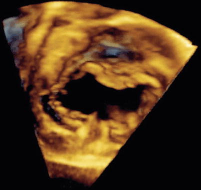
Fig. 8.34
Three-dimensional image obtained by transesophageal echocardiography in an older child displaying en face view of a complete atrioventricular septal defect. Note the detailed definition of the common atrioventricular valve components (Image by courtesy of David A. Roberson, M.D.)
Availability of 3D TEE using miniaturized probes in the future should allow for improved intraoperative morphologic definition of the repaired AV valve, potentially providing the surgeon with information that would allow appropriate manipulation of the valve leaflets at the time of surgery, thereby reducing the incidence of postoperative AV valve problems.
Congenital Mitral Valve Anomalies
Congenital mitral valve anomalies are rare in children but can have serious implications. These malformations include: (1) mitral stenosis, (2) parachute deformity, (3) supravalve mitral ring, (4) double-orifice mitral valve, (5) isolated cleft in the mitral valve, (6) mitral arcade, (7) straddling mitral valve, and (8) congenital valvar regurgitation.
The discussion that follows reviews the morphologic features that characterize each of these lesions and addresses relevant aspects of management, focusing on surgical approaches. A brief overview of the pathophysiology of mitral valve disease is presented. The role of TEE in the evaluation of these lesions is discussed, including goals of the preoperative examination, aspects of interest in the TEE study for each of the anomalies, assessment of the most commonly associated valvar functional abnormalities, and the postoperative interrogation. The experience to date regarding the applications of 3D imaging in congenital mitral valve anomalies is summarized.
Specific Anomalies
Morphologic Features and Management
Congenital Mitral Stenosis
Morphology—Congenital mitral stenosis was detected in 1.2 % of autopsied patients with CHD and in 0.42 % of all cardiac patients [58]. As an isolated entity this lesion occurs very rarely. Most commonly it is found within the context of mitral valve hypoplasia associated with Shone’s complex (discussed below) or in combination with other congenital pathology such as aortic coarctation [59]. Congenital mitral stenosis is usually characterized by abnormalities of all valve components and as such is defined by dysplasia of the entire mitral valve apparatus, i.e., thickened valve leaflets with rolled edges, short tendinous chords, and obliterated interchordal spaces. The lesion can also occur with papillary muscle(s) underdevelopment [12]. Although the clinical features are most notably those associated with obstruction to left ventricular inflow, valvar regurgitation also represents a manifestation of the disease.
Management Considerations—Congenital mitral stenosis is a difficult lesion to manage in infancy, accounting for significant morbidity and mortality. Interventions are necessary when obstruction is significant enough to cause symptoms. Since the pathology is complex in nature, aggressive medical management is always attempted first consisting primarily of diuretic therapy. Catheter-based procedures have been used in an effort to decrease the transvalvar mitral gradient and achieve symptomatic improvement [60]. Depending on the nature of the pathology, various surgical techniques have been applied in an effort to alleviate the obstruction [61]. These include valvotomy, commissurotomy, splitting of chordal structures and/or papillary muscles. In contrast to acquired mitral stenosis resulting from rheumatic heart disease, in most cases of congenital mitral stenosis commissurotomy is not adequate as the sole approach. Alternate strategies to valve repair include: (1) mitral valve replacement, in some cases requiring suturing the prosthesis in supra-annular position or annular enlargement; (2) placement of conduits between the left atrium and left ventricle, including replacement of the mitral valve with a pulmonary autograft (Ross II procedure); (3) single ventricle palliation, particularly in the presence of concomitant left-sided obstructive lesions; and (4) cardiac transplantation.
Parachute Mitral Valve
Morphology—A single papillary muscle in the left ventricle is the hallmark of a parachute mitral valve. Tendinous chords from the mitral valve leaflets insert onto this papillary muscle, or closely associated groups of papillary muscles, leading to the formation of the parachute deformity. A parachute mitral valve is commonly associated with other left-sided obstructive heart lesions. The constellation of lesions that include a parachute mitral valve, supravalvar mitral ring, subaortic stenosis, and coarctation of the aorta is referred to as Shone’s complex [62]. An incomplete (partial) form or variant implies the presence of fewer than these four components. A concomitant supravalvar mitral ring was recognized in 71 % of the patients with a parachute mitral valve deformity in one series, making it the most frequently detected left heart obstructive lesion in the presence of a parachute mitral valve [63]. The association of a parachute mitral valve with LVOTO is well established; however, mitral stenosis may also be associated with RVOTO, e.g. tetralogy of Fallot [64, 65].
Management Considerations—The surgical repair of a parachute mitral valve creating stenosis is challenging as full visualization of the mitral support apparatus, particularly in young patients can be extremely difficult, even more so in the case of concomitant left-sided obstructed lesions. In a case series of 12 patients with congenital mitral stenosis (9 of a parachute-type) the pathology was approached through an apical left ventriculotomy [66]. The management of this lesion may involve splitting of chordal structures and division of the single or closely spaced papillary muscle(s) enhancing the egress of left atrial blood into the left ventricle. The success rate of these types of interventions in alleviating the obstruction may be variable and likely significantly influenced by the associated lesions.
Supravalvar Mitral Ring
Morphology—A supravalvar mitral ring is a membrane lying in the funnel of the mitral valve leaflets, constricting left ventricular inflow. This anomaly almost always exists as part of a complete or partial Shone’s complex, and is rarely an isolated lesion. Therefore, a supravalvar mitral ring should be strongly suspected when typical lesions comprising the Shone’s complex are present and when the annulus of the mitral valve is hypoplastic. Conversely, identification of a supravalvar mitral ring should prompt a search for the other cardiac defects associated with Shone’s complex.
Management Considerations—Resection of a mitral valve ring is accomplished by peeling away the obstructive web from the surface of the leaflets on the left atrial aspect of the valve. In the majority of cases this is successful in relieving the inflow obstruction and allowing for the valve leaflets to move freely during diastole. At the time of surgery other lesions are addressed as indicated. This lesion, if the main cause of mitral inflow obstruction, is associated with a better prognosis as compared to other mitral valve pathology, thus identification of this particular entity is important when a patient presents with mitral stenosis.
Double-Orifice Mitral Valve
Morphology—Double-orifice mitral valve, an uncommon mitral valve lesion found in 1 % of autopsied cases of CHD, may lead to mitral stenosis, mitral regurgitation or both [67]. Various nomenclature (classic form, double parachute mitral valve) and classification schemes (complete bridge type, incomplete type, and hole type) have been proposed for this lesion based on the size and location of the two mitral valve orifices [23, 24, 67]. For practical purposes two morphological subtypes can be considered: one subtype is caused by a fibrous tissue ‘bridge’ across the left-sided orifice and is associated with AVSDs (Fig. 8.12, Video 8.7) [68]. The second subtype is caused by duplication of the mitral orifice, with each sub-orifice supported by its own tensor apparatus (Fig. 8.35) [12, 24]. These two forms cannot be easily distinguished from each other by echocardiography. Double-orifice mitral valve can also be found in the setting of a primum ASD, truncus arteriosus, left heart obstructive lesions, the CHARGE association (coloboma of the eye, heart defects, choanal atresia, growth retardation, genital and/or urinary abnormalities, ear abnormalities, and deafness), and other lesions [67, 69].
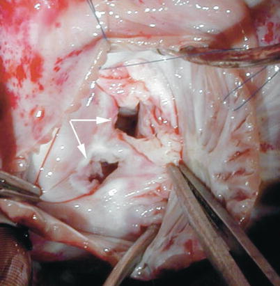
Fig. 8.35


Intraoperative photograph taken from a patient with duplication of the mitral valve (double-orifice mitral valve) showing the two distinct valve orifices (arrows)
Stay updated, free articles. Join our Telegram channel
Full access? Get Clinical Tree
