Assessment of the Aortic Valve
Christopher A. Troianos
Transesophageal echocardiography (TEE) is used intraoperatively to evaluate aortic valve anatomy, function, and hemodynamics. The application of Doppler echocardiography (pulsed wave, continuous wave, and color) with two-dimensional imaging allows for the complete evaluation of stenotic and regurgitant lesions. Qualitative and quantitative assessment permits informed decisions regarding surgical intervention, the type of intervention (repair versus replacement), correction of inadequate surgical repair, and reoperation for complications. Prebypass TEE evaluation also identifies myocardial and valvular abnormalities associated with aortic valvular lesions, and determines the size of valve to be implanted. There are several reasons why valve sizing is important. The size of the valve is always a consideration in deciding whether a valve with only moderate stenosis should be replaced. Patients with small annular diameters may not derive a significant benefit from aortic valve replacement. Preoperative valve sizing is also important when valves of limited availability are to be implanted, i.e., homografts (1). For patients undergoing aortic valve replacement for aortic stenosis, intraoperative TEE has been shown to alter the surgical plan in 13% (Table 15.1) (2).
Intraoperative TEE among patients with known aortic valve disease undergoing valve replacement is used to confirm the preoperative diagnosis and determine the etiology of valve dysfunction. High-resolution images, owing to the close proximity of the valve and the esophagus, permit accurate diagnosis of the mechanism of valve dysfunction, a key aspect for determining the feasibility of repair versus replacement. The vast majority of aortic valves suitable for repair have regurgitant lesions rather than stenotic lesions. Valve repair for patients with aortic dissection involves resuspension of the cusps and is easily performed and highly successful in the absence of additional leaflet pathology. Valve repair techniques and pathology suitable for repair are discussed later in this book.
TABLE 15.1. Limitations to Determination of Aortic Valve Area by Planimetry | ||||||||||||
|---|---|---|---|---|---|---|---|---|---|---|---|---|
|
Postoperatively, TEE is used to evaluate the success of repair or function of the prosthetic valve. The degree of residual aortic insufficiency is an important aspect of valve repair evaluation. It determines the need for further surgery and possible valve replacement. The number and area of regurgitant jets present after aortic valve replacement are less than after mitral valve replacement, but are a similar percentage decrease of regurgitant jet area after protamine administration (3). Patients undergoing the Ross procedure for autograft replacement of their aortic valves also require evaluation of the prosthetic pulmonic valves.
TEE evaluation of left ventricular function is important postoperatively because of the inherent low ventricular compliance present among patients with left ventricular hypertrophy due to long-standing aortic stenosis or chronic hypertension. Left ventricular volume is more accurately determined by two-dimensional echocardiographic assessment of LV cross-sectional area than by filling pressures measured with a pulmonary artery catheter.
Characteristically, patients with low LV compliance often require volume infusion despite high filling pressures in the post-bypass period. Accurate determination of optimal volume status requires TEE. Clinical information provided by TEE allows appropriate hemodynamic management of patients with aortic valve disease undergoing aortic valve and nonaortic valve surgery before, during, and after general anesthesia.
Characteristically, patients with low LV compliance often require volume infusion despite high filling pressures in the post-bypass period. Accurate determination of optimal volume status requires TEE. Clinical information provided by TEE allows appropriate hemodynamic management of patients with aortic valve disease undergoing aortic valve and nonaortic valve surgery before, during, and after general anesthesia.
A comprehensive perioperative TEE examination performed in patients undergoing nonaortic valve surgery may reveal aortic valve disease in patients in whom the diagnosis was not previously apparent. It is important to identify aortic valvular disease because of the surgical and anesthetic implications associated with both aortic stenosis and regurgitation. The increased population of elderly patients presenting for surgery has increased the prevalence of calcific aortic stenosis. Identification of significant aortic stenosis is important for anesthetic management during noncardiac surgery and for surgical management during nonaortic valve cardiac surgery. Aortic valve replacement after previous coronary artery bypass grafting is associated with higher mortality than combined aortic valve and coronary bypass surgery (4). Therefore, it is important to identify even moderate aortic stenosis during coronary bypass surgery, and to consider combination surgery to avoid the higher mortality associated with reoperation. Certain patients have a rapid progression of aortic stenosis, while others have a slower progression. Patients with rapid progression tend to be elderly men with associated coronary artery disease (5,6), or individuals with a smoking history, hypercholesterolemia, and elevated serum creatinine levels (7).
APPROACH
High-resolution images of the aortic valve provided by TEE result from the close proximity of the valve to the esophagus. The anatomic plane of the aortic valve is oblique compared with the plane of the esophagus, which is longitudinal within the body. The right, posterior aspect is inferior to the left anterior aspect of the valve (Fig. 15.1). The implication for TEE imaging is that the transducer must be flexed anteriorly and to the left from the transverse plane of the patient, to align the imaging plane with the plane of the aortic valve. Alternatively, a multiplane TEE probe is rotated forward to between 30 degrees and 60 degrees with anteflexion to develop the short-axis view of the valve (Fig. 15.2). This view is important for tracing the aortic valve orifice area using planimetry and for identifying the site of aortic insufficiency using color flow Doppler. Rotating the multiplane angle forward to between 110 degrees and 150 degrees (orthogonal to the short-axis view) develops the midesophageal aortic valve long-axis (ME AV LAX) view (Fig. 15.3). This view provides imaging of the left ventricular outflow tract, aortic valve, and aortic root to differentiate valvular from subvalvular and supravalvular pathology.
 FIGURE 15.1. Illustration of the anatomic orientation of the aortic valve and Sinuses of Valsalva within the heart. The aortic valve consists of three cusps: right (R), left (L), and noncoronary (N). The right and posterior aspects of the valve are inferior to the left and anterior aspects of the valve. SVC, superior vena cava; IVC, inferior vena cava. |
Hemodynamic assessment of antegrade and retrograde aortic valve flow requires a parallel orientation of blood flow and the Doppler beam (Fig. 15.4). The midesophageal views used for two-dimensional evaluation are inadequate for this assessment because blood flow is perpendicular to the Doppler beam. Conversely, the two transgastric views are more useful for interrogating flow across the aortic valve, but not as useful for detailed two-dimensional anatomic assessment due to the far field position of the aortic valve in these views. The deep transgastric long-axis (deep TG LAX) view is developed from the transgastric mid short-axis view by advancing the probe and flexing the probe to the left until the aortic valve is viewed in the middle or left side of the image in the far field (Fig. 15.5). The transgastric long-axis (TG LAX) view is developed from the transgastric mid short-axis view by rotating the transducer forward from 0 degrees to between 90 and 120 degrees until the aortic valve is viewed on the right side of the image in the far field (Fig. 15.6). Usually one or the other transgastric approach allows sufficient imaging to accomplish aortic valve flow measurement. It is important for the echocardiographer to become familiar with both approaches, because these
views are often difficult to obtain and require considerable practice and expertise. Stoddard et al. demonstrated 56% feasibility among the first 43 patients studied, as compared to 88% feasibility among the latter 43 patients studied suggesting a significant learning curve in measuring aortic valve blood flow velocity via the transgastric approach (8).
views are often difficult to obtain and require considerable practice and expertise. Stoddard et al. demonstrated 56% feasibility among the first 43 patients studied, as compared to 88% feasibility among the latter 43 patients studied suggesting a significant learning curve in measuring aortic valve blood flow velocity via the transgastric approach (8).
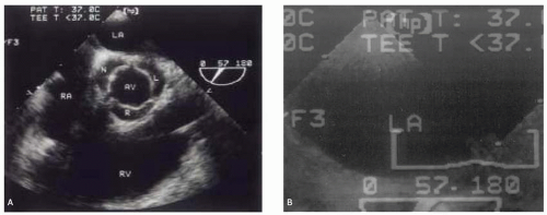 FIGURE 15.2. Transesophageal echocardiogram of the midesophageal aortic valve short-axis view during systole (A) and diastole (B). A multiplane probe at 57 degrees provided this view in which all three aortic valve cusps are similar in size and appearance, indicating a true short-axis cross section. The aortic valve (AV) is identified by the right (R), left (L), and noncoronary (N) cusps. LA, left atrium; RA, right atrium; RV, right ventricle. |
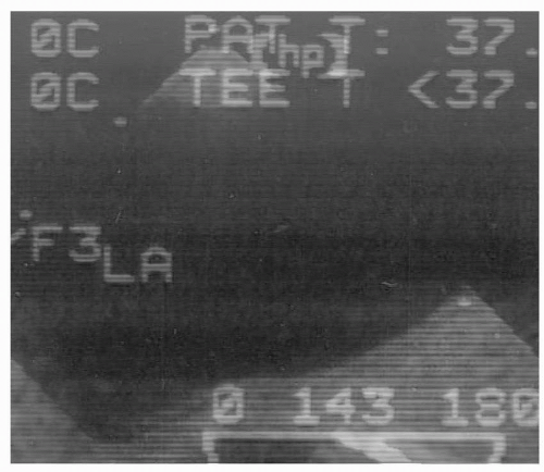 FIGURE 15.3. Transesophageal echocardiogram of the midesophageal aortic valve long-axis view during systole. A multiplane probe at 143 degrees provided this view of a normal aortic valve with leaflets (arrows) that open parallel to the aortic walls. The proximal ascending aorta is also imaged in this view. LA, left atrium; LV, left ventricle; RV, right ventricle. |
STRUCTURES
The aortic valve is composed of three cusps that are associated with three bulges or pouch-like dilations in the aortic wall called the Sinuses of Valsalva (Fig. 15.1). Proximal to the aortic valve, the left ventricular outflow tract consists of the inferior surface of the anterior mitral leaflet, the ventricular septum, and the posterior left ventricular free wall. A normal aortic valve appears as two thin lines that open parallel to the aortic walls in the midesophageal aortic valve long-axis (ME AV LAX) view.
The ascending aorta and LVOT are also inspected using this view (Fig. 15.3).
The ascending aorta and LVOT are also inspected using this view (Fig. 15.3).
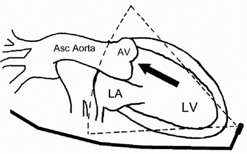 FIGURE 15.4. Illustration of the TEE probe position for the deep transgastric view of the aortic valve that allows a parallel orientation of blood flow through the aortic valve (AV) and left ventricular outflow tract (arrow). LA, left atrium; LV, left ventricle; Asc, ascending. From: Troianos CA. Aortic Valve. In Konstadt SN, Shernans, & Okay, Eds. Clinical Transesophageal Echocardiography: A Problem-Oriented Approach, 2nd ed., with permission. |
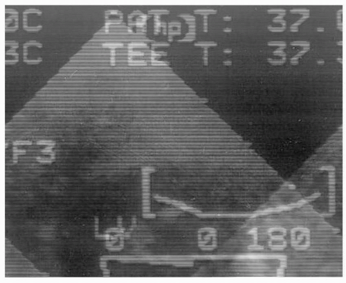 FIGURE 15.5. Transesophageal echocardiogram of the deep transgastric view. AV, aortic valve; LA, left atrium; LV, left ventricle; AO, ascending aorta; MV, mitral valve; RV, right ventricle. |
PATHOLOGY
Pathophysiology of Aortic Stenosis
The most frequent causes of aortic stenosis are calcific stenosis in the elderly, rheumatic valvulitis, and congenital anomalies (bicuspid, rarely unicuspid) that lead to accelerated leaflet calcification and restriction. The mechanism of stenosis occurs from calcification of the leaflets (calcific, rheumatic, or congenital) or commissural fusion (usually rheumatic). Subaortic stenosis (subaortic membrane or ridge, and asymmetric septal hypertrophy) and supravalvular stenosis (narrowed aortic root) mimic aortic stenosis, but do not represent true valvular stenosis. Many of the echocardiographic techniques used for hemodynamic assessment of the aortic valve, however, can also be used to evaluate the severity of subvalvular and supravalvular pathology. Asymmetric septal hypertrophy or hypertrophic obstructive cardiomyopathy is discussed later in this book.
 FIGURE 15.6. Transesophageal echocardiogram of the transgastric long-axis view. AV, aortic valve; AORTA, aortic root; LA, left atrium; MV, mitral valve; LV, left ventricle. |
Echocardiographic Evaluation of Aortic Stenosis
An important sign of aortic stenosis is leaflet doming during systole (Fig. 15.7). The leaflets are curved toward the midline of the aorta instead of parallel to the aortic wall. Leaflet doming is such an important observation that this finding alone is sufficient for the qualitative diagnosis of aortic stenosis. Coincident with doming is reduced leaflet separation (<15 mm), which is appreciated in both the short- and long-axis views of the aortic valve. The short-axis view of the aortic valve (Fig. 15.8) permits evaluation of leaflet motion and calcification, commissural fusion, and leaflet coaptation. This short-axis view (30 to 60 degrees) is used for measuring the aortic valve orifice area by two-dimensional planimetry, which provides good correlation
with other methods used for assessment of aortic stenosis (9). The probe is manipulated to provide the image with the smallest valvular cross-sectional area to ensure that the imaging plane is at the level of the leaflet tips, or smallest orifice. A cross section that is oblique or inferior to the leaflet tips overestimates the orifice size. The valve should appear circular in a true short-axis cross section as all three cusps are viewed simultaneously (9) and appear equal in shape. Multiplane TEE simplifies the location of the actual smallest orifice by imaging the aortic valve, first in long-axis view to identify the smallest orifice at the leaflet tips. The orifice is centered on the image display screen and the transducer position is stabilized within the esophagus as the multiplane angle is rotated backward to the short-axis view. The smallest orifice is traced and the two-dimensional cross-sectional area is displayed. Limitations to this technique are listed in Table 15.1 and include:
with other methods used for assessment of aortic stenosis (9). The probe is manipulated to provide the image with the smallest valvular cross-sectional area to ensure that the imaging plane is at the level of the leaflet tips, or smallest orifice. A cross section that is oblique or inferior to the leaflet tips overestimates the orifice size. The valve should appear circular in a true short-axis cross section as all three cusps are viewed simultaneously (9) and appear equal in shape. Multiplane TEE simplifies the location of the actual smallest orifice by imaging the aortic valve, first in long-axis view to identify the smallest orifice at the leaflet tips. The orifice is centered on the image display screen and the transducer position is stabilized within the esophagus as the multiplane angle is rotated backward to the short-axis view. The smallest orifice is traced and the two-dimensional cross-sectional area is displayed. Limitations to this technique are listed in Table 15.1 and include:
 FIGURE 15.7. Transesophageal echocardiogram of the midesophageal aortic valve long-axis view during systole in a patient with aortic stenosis. A multiplane probe at 138 degrees provided this view of an aortic valve with doming leaflets (arrows). Leaflet doming is a qualitative sign of stenosis. The proximal ascending aorta is also imaged in this view. LA, left atrium; LV, left ventricle. |
 FIGURE 15.8. Transesophageal echocardiogram of the midesophageal aortic valve short-axis view during systole in a patient with aortic stenosis. L, R, and N, left, right, and noncoronary aortic valve cusps, respectively; LA, left atrium; RA, right atrium; RV, right ventricle. |
Inability to obtain an adequate short-axis view
Heavy calcification, particularly posterior, that causes shadowing of the valve
The presence of “pinhole” aortic stenosis, in which the valve orifice cannot be identified
The short-axis view of the aortic valve identifies congenital abnormalities of the aortic valve, including bicuspid (Fig. 15.9) and unicuspid (Fig. 15.10) valves.
Doppler echocardiography is used to quantitate the severity of aortic stenosis by measuring transvalvular blood velocity. The peak pressure gradient is estimated from the peak velocity measurement using the modified Bernoulli equation:
 FIGURE 15.9. Transesophageal echocardiogram of the midesophageal aortic valve short-axis view in a patient with bicuspid aortic stenosis. Arrow, bicuspid aortic valve; LA, left atrium; RA, right atrium; RV, right ventricle; PA, pulmonary artery. |
Aortic Valve Gradient = 4 × (Aortic Valve Velocity)2
As previously mentioned, the midesophageal views of the aortic valve are not suitable for measuring transaortic velocity because accurate Doppler measurements require a
parallel alignment of the Doppler beam with the blood flow. The deep TG LAX view is developed by advancing the probe beyond the transgastric midpapillary and apical short-axis views, maximally anteflexing the probe and flexing it to the left (Fig. 15.5). This places the probe at the left ventricular apex with the ultrasound beam directed toward the base of the heart (Fig. 15.4). The left atrium appears in the far field, to the right of the aortic valve and aortic root. A parallel alignment with blood flow in the LVOT and through the aortic valve is thus achieved. A parallel alignment of the ultrasound beam and aortic valve flow can also be obtained with the TG LAX view. This view is developed from the transgastric midpapillary short-axis view by rotating the multiplane angle from zero to between 90 and 120 degrees. The left atrium appears on the right side of the screen and the aortic valve is in the far field (Fig. 15.6).
parallel alignment of the Doppler beam with the blood flow. The deep TG LAX view is developed by advancing the probe beyond the transgastric midpapillary and apical short-axis views, maximally anteflexing the probe and flexing it to the left (Fig. 15.5). This places the probe at the left ventricular apex with the ultrasound beam directed toward the base of the heart (Fig. 15.4). The left atrium appears in the far field, to the right of the aortic valve and aortic root. A parallel alignment with blood flow in the LVOT and through the aortic valve is thus achieved. A parallel alignment of the ultrasound beam and aortic valve flow can also be obtained with the TG LAX view. This view is developed from the transgastric midpapillary short-axis view by rotating the multiplane angle from zero to between 90 and 120 degrees. The left atrium appears on the right side of the screen and the aortic valve is in the far field (Fig. 15.6).
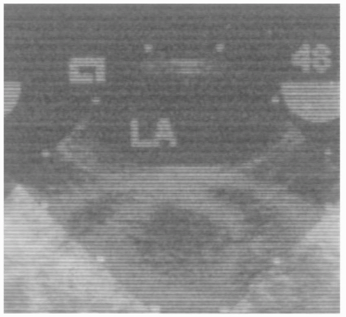 FIGURE 15.10. Transesophageal echocardiogram of the midesophageal aortic valve short-axis view in a patient with a unicuspid aortic valve as indicated by the arrows. LA, left atrium; RA, right atrium; RV, right ventricle. From Troianos CA. Perioperative Echocardiography. In: Troianos CA, ed. Anesthesia for the Cardiac Patient. St. Louis: Mosby, 2002, with permission. |
Color flow Doppler and the audible Doppler signal are useful for identifying the location of the narrow high velocity jet (Fig. 15.11). The continuous wave Doppler cursor is placed within the narrow, turbulent jet and the spectral Doppler display is activated. Accurate localization provides a distinctive audible sound and high velocity (> 3 m/sec) spectral Doppler recording that exhibits a fine, feathery appearance and a midsystolic peak (Fig. 15.12). Normal aortic valves have peak velocities of 0.9 to 1.7 m/sec in adults, and peak in early systole. More dominant and dense lower velocities are also evident on the spectral Doppler display of patients with aortic stenosis and represent the more laminar, lower velocities in the LVOT. Planimetry of the velocity over time spectral Doppler analysis of transaortic blood flow yields the velocity time integral (VTI) and an estimate of mean aortic valve gradient.
Stay updated, free articles. Join our Telegram channel

Full access? Get Clinical Tree


