Assessment in Mitral Valve Surgery


Assessment in Mitral Valve Surgery


Robert M. Savage

Taka Shiota

William J. Stewart

Marc Gillinov


HISTORICAL PERSPECTIVES

Over the last three decades, there have been great advances in mitral valve (MV) surgery closely affiliated with innovations in the intraoperative applications of echocardiography. In 1972, Johnson et al. reported the first use of echocardiography in MV surgery by demonstrating a successful open mitral commissurotomy using epicardial mmode (1). Frazin, Talano, and Stephanides subsequently demonstrated the ability to accurately measure valve size and flow velocities using a transducer passed into the esophagus on a thin cable (2). In the late 1970s, Hisanga et al. placed a two-dimensional (2-D) ultrasound transducer prototype on a flexible gastroscope (3). Kremer, Hanrath, Roizen et al. first reported the intraoperative use of transesophageal echocardiography for monitoring patients undergoing abdominal aortic aneurysm resections in 1982 (4,5). Goldman and colleagues demonstrated the potential intraoperative impact of echocardiography by detecting mitral regurgitation (MR), utilizing contrast-enhanced epicardial imaging in valve surgery (6). Takamoto et al. demonstrated the use of real-time color flow mapping during valve surgery (7).


IMPORTANCE OF INTRAOPERATIVE ECHOCARDIOGRAPHY (IOE) IN MV SURGERY

Early use of intraoperative guidance during MV repair surgery using Doppler color flow mapping was reported by Stewart and colleagues in 1986 (8). Since then, its use in guiding the intraoperative management of patients undergoing MV surgery has continued to expand. Intraoperative echocardiography (IOE) has demonstrated a unique ability to yield new diagnostic information impacting the surgical and hemodynamic management of patients in MV surgery (9,10,11,12,13). Based on such scientific evidence and expert opinion, the American College of Cardiology and the American Heart Association classified mitral valve repair and MV replacement (MVR) as Class I and IIA indications for intraoperative echocardiography (19). The ability of IOE to impact the outcome of surgical procedures involving the MV has established it as a universal diagnostic and monitoring standard of care for the intraoperative management of patients undergoing MV surgery (14,15,16,17,18).


IMPORTANCE OF MV SURGERY IN THE FUTURE OF CARDIAC SURGERY

Consequently, there is a growing demand for clinicians with an experienced understanding of the echocardiographic assessment of the MV and its use in the intraoperative decision-making process (20). Because of the increasing numbers of patients projected to undergo surgical interventions for MV dysfunction over the next 20 years, this demand will continue (21,22,23,24,25). These projections are based on our aging population (Fig. 28.1), the high incidence of significant MV disease in the elderly, and the large percentage of patients having surgery within 10 years of their initial diagnosis of MV dysfunction (26,27,28,29) (Figs. 28.2 and 28.3). Because of the many advantages that MV repair offers the patient, an expanding number of cardiac centers are developing a successful experience with MV repair in all etiologies (30,31,32). With this increasing probability of successful MV repair, the American College of Cardiology (ACC) and American Heart Association (AHA) Task Force on Practice Guidelines for the Management of Patients with Valvular Heart Disease have recommended earlier surgical referral for patients with MV dysfunction who are candidates with a high probability of successful MV repairs (MVRep) (33). Currently, the Society of Thoracic Surgeons STS database reports that only 33% of isolated MV procedures from reporting cardiac surgery programs are MV repairs (34). This is in contrast to the 90% incidence of MV repair reported by some cardiac centers experienced with MV repair (Fig. 28.4) (30,31,32). If the number of advanced MVRep procedures is to grow, it will require an increased availability of echocardiographic expertise throughout for the duration of such surgical procedures (20,33).


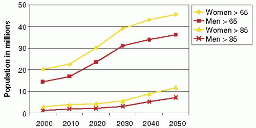
FIGURE 28.1. Population projections forecast the aging of America. By the year 2030, the United States Census Bureau estimates that 20% of individuals living in the United States will be over the age of 65.


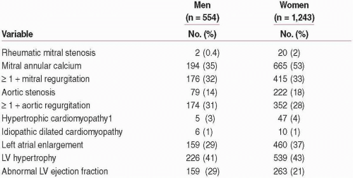
FIGURE 28.2A. Aronow et al. demonstrated that more than 30% of individuals over the age of 60 have greater than mild mitral insufficiency. Understanding that some patients have significant structural abnormalities of the valve and supporting apparatus, the incidence of clinical disease involving the mitral valve will likely increase. Aronow WS, Ahn C, Kronzon I of Echocardiographic Abnormalities in African-American, Hispanic, and White Men and Women Aged > 60 Years. Am J Cardiol 87(9): 1131-1133, 2001 May 1.


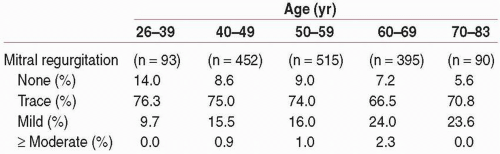
FIGURE 28.2B. The Framingham study population has demonstrated an increased incidence of mitral regurgitation associated with aging. More than 25% of individuals over the age of 60 demonstrated greater than mild mitral insufficiency.


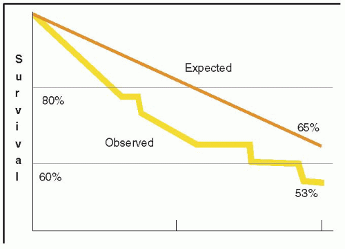
FIGURE 28.3A. There are wide ranges of long-term survival and freedom from operation in patients with MR. Enriquez-Sariano et al. compared the cardiac morbidity and long-term survival at 5 and 10 years in patients diagnosed with flail MV leaflet to normal survival for age. There was over a 6.0% excess mortality per year, with a 5- and 10-year survival of 65% and 53%, respectively. Patients with ejection fractions < 50% had a 10-year survival of 32%. Over 90% of patients had either received surgical intervention or expired at the end of 10 years. Timing of mitral valve surgery. Br Heart J; 28:79-85, Jan.


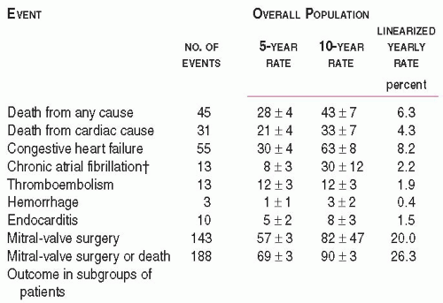
FIGURE 28.3B. Ling et al. and Enriquez-Sariano et al. have demonstrated that a high percentage of patients with structural mitral regurgitation either expire or have surgery within 10 years of their initial diagnosis. Timing of mitral valve surgery. Br Heart J; 28:79-85, Jan.


INTRAOPERATIVE ECHOCARDIOGRAPHY (IOE) AND CRITICAL ISSUES IN MV SURGERY

For patients who are scheduled for elective MV surgery, the purpose of the IOE exam is not to replace the preoperative diagnostic evaluation of the patient. The purpose of the precardiopulmonary bypass (pre-CPB) IOE exam is to confirm the severity of MV dysfunction and to refine the understanding of the mechanism of dysfunction, in addition to addressing those critical issues that guide the intraoperative management of the patient and ensure the results of the surgical intervention (Table 28.1). However, there are some unusual scenarios where decisions to perform, or not perform, MV surgery are made following the results of the IOE exam.


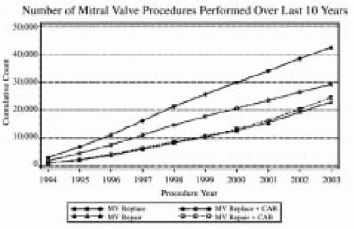
FIGURE 28.4A. The 2003 Executive Summary of the Society of Thoracic Surgeons documents the continued growth of mitral valve surgery. More than 30% of all mitral valve surgeries since 1994 involved a reconstructive approach to MV dysfunction (34). The percentage of MVRep versus replacements continues to increase.


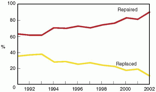
FIGURE 28.4B. The percentage of mitral valve repair procedures performed in patients undergoing isolated mitral valve surgery at the Cleveland Clinic has consistently increased since 1995.


  • The first of these involves patients with preoperative mild to moderate MR or MS who are undergoing another cardiac surgical procedure and confirmation of the decision to avoid MV surgery is desired. In these circumstances, customary monitors are placed, prior to induction, to better understand the patient’s baseline hemodynamics. During the intraoperative assessment, hemodynamics similar to those recorded at a preoperative echocardiographic exam or just prior to induction are reproduced.


    TABLE 28.1. Intraoperative Echocardiography Exam and Critical Issues in MV Surgery


    1.


    Confirm and Refine Preoperative Assessment


    Confirm MV dysfunction and severity


    Determine repairability of valve


    Refine pathoanatomy and mechanism


    Explain variances


    2.


    Determine the Need for Unplanned Surgical Intervention


    Secondary pathophysiology


    Associated abnormality


    Unrelated process


    3.


    Determine Cardiac Dysfunction Impacting Management


    Secondary pathophysiology


    Dysfunction associated with primary etiology


    Coexisting dysfunction


    4.


    Cannulation and Perfusion Strategy


    5.


    Address Surgical Procedure-Specific Issues


    6.


    Predict Complications


    7.


    Assess Surgical Results


    Initial and ongoing patient management


    Results of surgery


    Complications


  • The second such scenario is significant MV dysfunction that was either undiagnosed or is more severe than was determined by the preoperative evaluation. When the MR is of surgical severity, adding a mitral procedure is often a good idea, as long as it does not prohibitively increase the surgical risk-to-benefit ratio.


  • The final situation is finding MR that is significantly less than expected or absent. When findings of the pre-CPB IOE suggest a change in the operative plan, considerable thought must be given to the reasons for this discrepancy. However, intraoperative conditions may underestimate the amount of MR present under “street conditions” that have led to the well-established plan to perform MV surgery. We often challenge such patients with afterload stress (volume loading and phenylephrine) to see if the underrepresentation of MR might be a transient or misleading issue. When the operative mission is changed substantially, it is helpful to contact the consultative clinicians who have been involved in the long-term management of the patient. These are also situations where it is advisable to use the most quantitative assessments of severity, such as those recommended by the ASE Nomenclature and Standards Committee Task Force on Native Valve Regurgitation (35).

Because MV repair is the preferred treatment for MV dysfunction of all etiologies, every patient is considered a potential candidate for repair. The most significant surgical issues that the initial intraoperative exam assists in resolving are:


  • The probability of successful MV repair


  • The necessity to perform other surgical interventions related to the patient’s secondary, associated, or coexisting cardiovascular dysfunction.


  • The assessment of the results of the surgical procedure

The surgeon’s ability to repair the MV is determined by a number of factors, including the underlying etiology, the structural integrity of the anatomic components of the mitral valve apparatus (MVAp), and the mechanism of dysfunction caused by the underlying pathologic process (36,37). The surgeon’s strategy for repair or replacement is a result of examination of the anatomy of the MVAp in correlation with the functional assessment of the MVAp provided by the IOE exam. The direct inspection of the MVAp includes an evaluation of the left atrium (size and secondary regurgitant lesions), annulus (secondary jet lesions, degree dilatation, scarring, and deformity), valve leaflets (thickness, motion, and coaptation), chordae (redundancy, thickness, and presence of fusion or rupture), papillary muscle (elongation, infarct, or rupture), and the free wall of the left ventricle (LV). From this information, the surgeon establishes the most effective line of attack, incorporating a variety of MVRep techniques or replacing the valve.

For the surgeon who is less experienced in mitral valve repair surgery, the IOE exam contributes to an accelerated learning curve enabling him or her to immediately compare the findings of their direct inspection with those of the echocardiography examination. For the more accomplished surgeon who can develop a strategy from what he has learned from experience with the IOE exam, the echocardiographer provides greater assistance with the post-CPB assessment of the repair and, if necessary, determining the mechanism(s) of an initially unsuccessful MVRep or other potential post-CPB complications. However, even with the experienced surgeon, the IOE exam serves as a final preintervention diagnostic screen for previously undiagnosed but significant valve or other cardiac dysfunction.

The decision to perform additional surgical interventions is made during the pre-CPB evaluation for significant secondary pathophysiology and associated or coexisting cardiovascular disease. Chaliki et al. discovered that in 1,265 patients undergoing MV surgery, 146 (12%) had new precardiopulmonary bypass (pre-CPB) findings that altered their intraoperative management (38). Sheikh et al. evaluated 154 consecutive patients who had IOE assessment in conjunction with a valve operation. The IOE yielded unsuspected findings prior to cardiopulmonary bypass that either modified or changed the planned operation in 19% of patients (39). Other important issues that the IOE exam addresses include the cannulation-perfusion and myocardial protection strategy, specific surgical procedure-related issues (i.e., need for sliding annuloplasty),
determination of the probability of certain post-CPB complications, and assessment of the results of surgical intervention. The information provided from the systematic IOE exam provides the intraoperative team with an up-to-date road map, which will guide the surgical decision-making process and direct the hemodynamic management of the patient throughout the operation (40).


ORGANIZATION OF CHAPTER

Intraoperative echocardiography has become an integral part of the comprehensive management of the patient undergoing MV surgery. As we will see, it has a direct influence on the intraoperative decision-making process for the surgical and hemodynamic management of the patient. It has a lasting impact on long-term outcome. The majority of patients having MV surgery are customarily scheduled following a thorough and extensive evaluation. Consequently, the intraoperative focus shifts from one of exhaustive assessment of severity of MV dysfunction to those essential issues that will impact the course of the surgical intervention and, ultimately, patient outcome. These issues include an understanding of the mechanism(s) of MV dysfunction, the potential repairability of the valve, and the patient’s intraoperative management. Consequently, we will emphasize the technique of the intraoperative exam used for developing a three-dimensional understanding of the etiology and mechanics causing dysfunction of the MVAp. This chapter will provide an understanding of how echocardiography is incorporated into the daily management of patients undergoing MV surgery. It will focus on those aspects of the intraoperative examination that permit an accurate and efficient assessment of the critical issues that must be addressed for patients undergoing MV surgery. To reinforce the fundamental considerations in the chapter, a summary of “Key Concepts” is provided at the beginning and a brief review at the conclusion. An overview of the surgical anatomy of the mitral valve apparatus (MVAp) and the imaging planes that are used in its intraoperative assessment are provided. We will then concentrate on the efficient approach to the systematic echocardiographic exam for patients undergoing MV surgery; this includes the evaluation of MV pathology, secondary pathophysiology, as well as associated or coexisting cardiovascular disease. Finally, we concentrate on specific additional details that are required from the intraoperative examination to ensure the successful outcome of patients undergoing the wide range of MV surgical interventions.


KEY CONCEPTS


  • The MVAp is a complex structure consisting of the fibrous cardiac skeleton, saddle-shaped mitral annulus, mitral valve leaflets, chordae, papillary muscles, and ventricular wall complex. Pathologic processes that lead to structural damage to the anatomic integrity of the components of the MVAp may result in mitral valve dysfunction.


  • The purpose of the intraoperative echocardiographic IOE exam is to confirm and refine the patient’s preoperative assessment as issues that are critical to their intraoperative management are resolved.


  • Mitral valve repair is the treatment of choice for MV dysfunction resulting from all etiologies because of its superior long-term survival, preservation of ventricular function, and greater freedom from thromboembolism, endocarditis, and anticoagulatant related complications.


  • For patients scheduled for elective MV surgery, the most significant surgical issues that the IOE exam assists in resolving include the repairability of the MV apparatus (MVAp), the necessity to perform other surgical interventions, and the postcardiopulmonary bypass assessment of the surgical procedure and complications.


  • The feasibility of MVRep is guided by the real-time assessment of the mitral valve apparatus and the mechanism of dysfunction by the IOE exam, in conjunction with the surgeon’s direct inspection of the MVAp.


  • The IOE exam is performed according to the unique demands of the cardiac surgical environment, with the pre-CPB and post-CPB exams organized by priority to ensure that critical issues are addressed should the patient require the initiation of CPB.


  • The pre-CPB IOE exam determines the severity and anatomic mechanism of MV dysfunction, in addition to assessing secondary or associated pathophysiology, cannulation-perfusion strategy, the potential for post-CPB complications, and providing an ongoing assessment of cardiac function.


  • The post-CPB IOE exam provides a quality assurance safety net with immediate assessment of the surgical procedure and diagnosis of complications related to the surgery or disease process.


  • The IOE exam relies upon integrated methods of severity assessment that may be efficiently performed in a multitasking environment. The methods included here are those recommended by the American Society of Echocardiography’s Task Force on Native Valvular Regurgitation. They have been validated by accepted standards to ensure their ability to reliably guide the intraoperative decision-making process.


  • The severity of mitral valve dysfunction is evaluated intraoperatively by the integration of multiple two-dimensional and Doppler parameters. The reliance on any one method of assessing severity is weighted by dependability of the specific data acquired and the quantitative reliability of a particular technique. Such an integrated approach minimizes the individual measurement error inherent to each.


  • Color flow Doppler is a method to screen for severe MV dysfunction. Its use as a stand-alone method of severity assessment to guide the intraoperative decision-making process is not recommended (35).


MITRAL VALVE APPARATUS (MVAp)


Normal Anatomy of the Mitral Valve Apparatus

The mitral valve apparatus is the anatomical term describing the structures associated with MV function. It consists of the fibrous skeleton of the heart, the mitral annulus, mitral leaflets, mitral chordae, and the papillary muscle-ventricular wall complex (Fig. 28.5) (41,42,43,44,45). This complex structure is comprised of the tensor apparatus (fibrous annulus, left ventricular myocardium from the fibrous MV annulus to the base of papillary muscle insertion, the papillary muscles, and the chordae) and the valvular apparatus (valve leaflets). Maintenance of the continuity of the tensor and valvular apparatus is essential for normal ventricular and MV function (41,42).


Fibrous Skeleton

The fibrous skeleton of the heart is formed by the three U-shaped cords of the aortic annulus and their extensions, forming the right trigone, left trigone, and a smaller fibrous structure from the right aortic coronary cusp to the root of the pulmonary artery (42,44,46). This skeleton plays a primary function in structural support of the heart. The U-shaped cords of the aortic annulus merge to form the right and left fibrous trigone (46). A fibrous skeleton extends between the aortic and mitral annulus and is referred to as the intervalvular fibrosa (44,45,46).


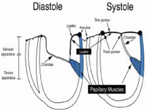
FIGURE 28.5. The mitral valve is composed of five distinct anatomic structures including the mitral annulus, valve leaflets, chordae, papillary muscles and ventricular wall. Dysfunction of any one of these structures will eventually interfere with the effective coaptation of the valve leaflets with associated valve regurgitation and its associated sequelae.


Mitral Annulus (Fig. 28.7 A,B, C, and D)

Fibrous tissue extends from the left and right atrioventricular orifices, forming the annulus of the mitral and tricuspid valves (41,43,47,48). The mitral annulus serves as a transition between the left atrium, mitral leaflets, and left ventricle. The base of the anterior mitral valve leaflet (AMVL) is closely associated with the left trigone, inter-trigonal space, and right trigone area (Fig. 28.6) (44). The fibrous mitral annulus is an ellipsoidal, three-dimensional, saddle-shaped structure that thins posteriorly where it is more prone to dilatation in pathologic conditions (Figs. 28.7A, 28.7B and 28.7C) (48). The resulting increased tension on the posterior valve leaflet at its thinnest region contributes to the 60% incidence of chordal tears. The annulus is saddle-shaped during systole but changes to a circular shape in diastole (Fig. 28.7B) (36). The anterior mitral annulus is more rigid. It undergoes less change in shape during the cardiac cycle and is less prone to dilation (47,48). The U-shaped minor axis of the ellipsoid annulus is best visualized and measured in the midesophageal long-axis (LAX) imaging plane, whereas the U-shaped major axis is best visualized and measured in the ME commissural imaging plane (Fig. 28.7C). Accordingly, prolapse of valve leaflets (extension above the plane of the mitral annulus) is more accurately assessed in the long-axis imaging plane due to its more basal position compared to the commissural imaging plane (41,46,48).


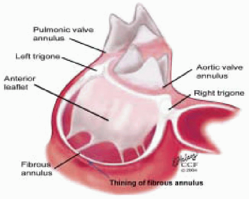
FIGURE 28.6. The fibrous skeleton of the heart is formed by the three U-shaped cords of the aortic annulus and by extensions forming the right trigone, left trigone and a smaller fibrous structure from the right aortic coronary cusp to the root of the pulmonary artery. The skeleton provides a rigid structural foundation for the valves and chambers of the heart. The anterior leaflet attaches to the fibrous skeleton at the rigid intervalvular fibrosa, giving it less flexibility and a tendency to dilate anteriorly. The fibrous tissue of the annulus thins posteriorly (red arrow).


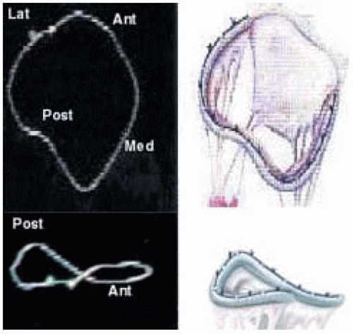
FIGURE 28.7A. Three-dimensional shape of MV annulus and with a three-dimensional annuloplasty ring.


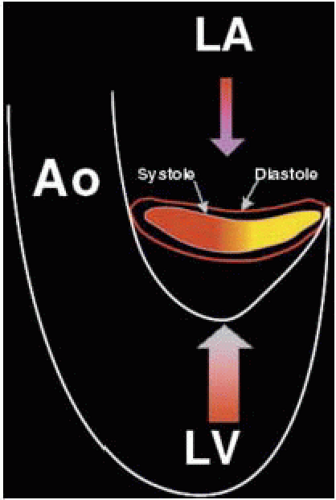
FIGURE 28.7B. During systole, the circular annulus circumferentially narrows, becoming a 3-dimensional saddle-shaped annulus. This effectively decreases the size of the MV orifice. Fibrosis or calcification of the annulus interferes with its mobility and effectively increases the area requiring leaflet apposition to prevent regurgitant flow.


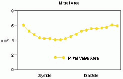
FIGURE 28.7C. The fibrous mitral annulus is an ellipsoidal saddle-shaped structure, which thins posteriorly where it is more prone to dilatation in pathologic conditions. During systole the annulus decreases in size and becomes saddle-shaped. In diastole it changes to a circular shape. The anterior mitral annulus is more rigid and has minimal change in shape during the cardiac cycle.


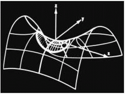
FIGURE 28.7D. The 3-dimensional shape of the annulus demonstrating the most superior (farthest from apex) points in the anterior-posterior orientation (ME LAX TEE plane). The most inferior (nearest the apex) points of the annulus are in the inferoseptal and anterolateral plane (ME Com TEE plane). Using the ME Com imaging plane will result in lower specificity in the diagnosis of MV prolapse or excessive leaflet motion.


Mitral Valve Leaflets

Morphologically, the MV has two leaflets referred to as the anterior and posterior leaflets (AMVL and PMVL).
The mitral leaflets are attached to the fibrous annulus and to the free wall of the ventricle via papillary muscles and the primary edge and secondary midvalve chordae (43,44,45). The anterior mitral leaflet (AMVL) is triangular in shape and attached to the fibrous body at the left coronary cusp and anterior half of the noncoronary cusp of the aortic valve. The AMVL comprises about 55% to 60% of the total MV area and about 30% of the annular circumference (42,43). The posterior leaflet comprises 40% to 45% of the MV area and attaches to the mitral annulus posteriorly (Fig. 28.8) (41,42). As the heart normally lies in the chest cavity, the PMVL height (length) is usually less than the height of the AMVL (Fig. 28.9). During systole, the leaflets come together along a “line of coaptation,” which extends anteriorly to the anterolateral commissure and posteriorly to the posteromedial commissure (Fig. 28.10). During diastole, the middle of the leaflet initially moves toward the ventricle followed by opening of the valve at the leaflet edges (44,48) (Fig. 28.11). The middle of the leaflet opens before the commissures. Once the leaflet extends fully it may flutter and drift upwards until the atrial contraction. The surface of each leaflet is divided into a rough zone (coapting surface where primary and secondary chords attach), clear zone (midportion of leaflet, secondary chordae attachments), and basal zone (leaflet attachment to the annulus, insertion of posterior tertiary chordae) (49). The basal two-thirds of each leaflet are smoother than the distal third. The combined surface area of the mitral leaflets is twice that of the mitral orifice. This permits large areas of coaptation with a normal 3 mm to 5 mm of residual leaflet apposition distal to the point of coaptation (43,44,45). This line of coaptation between the two leaflets is semicircular and influences the segments of the valve leaflets, which are visualized in the standard imaging planes (Fig. 28.12). There is a range of mitral commissural orientations due to variation in the degree of annular size and rotation of the heart caused by individual variations and enlargement of chambers. Consequently, the commissure may be oriented more clockwise in some individuals, explaining the variability of segmental mitral anatomy visualized at the same transducer rotation in different patients (Fig. 28.13). The posterior MV leaflet consists of three scallops that are separated by prominently distinct indentations called clefts (Fig. 28.14). These scallops are referred to as lateral, middle, and medial. The lateral scallop is closest to the left atrial appendage (43,45). The anterior leaflet, for purely descriptive purposes, is segmented into the corresponding lateral, middle, and medial thirds.


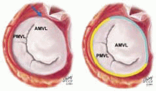
FIGURE 28.8. The MV has two leaflets referred to as the anterior and posterior leaflets (AMVL and PMVL). The mitral leaflets are circumferentially attached to the fibrous annulus. The anterior mitral leaflet (AMVL) is attached to the same fibrous body as the left coronary cusp (→). The anterior mitral valve leaflet (AMVL) comprises about 55% to 60% of the total MV area and about 30% to 40% of the annular circumference (—). The posterior leaflet comprises 40% to 45% of the MV area, and 60% to 70% of the circumference attaches to the mitral annulus posteriorly.


FIGURE 28.9. The MV has two leaflets referred to as the anterior and posterior leaflets (AMVL and PMVL). As the heart normally lies in the chest cavity, the PMVL height (length) is usually less than the height of the AMVL.


FIGURE 28.10. During systole, the leaflets come together along a “line of coaptation,” which extends anteriorly to the anterolateral commissure (ALC ) and posteriorly to the posteromedial commissure (PMC).


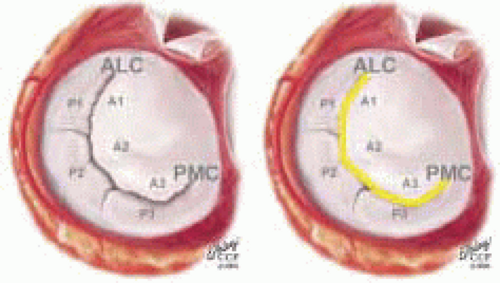
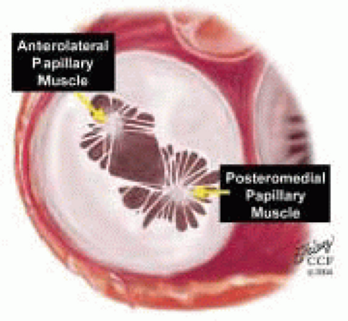
FIGURE 28.11. During diastole, the middle of the leaflet moves toward the ventricle with opening of the valve at the leaflet edges. The middle of the leaflet opens before the commissures. Once the leaflet extends fully, it may loiter until atrial contraction.


Chordae Tendineae

Chordae are fibrous attachments extending from the leaflet to the papillary muscles and posterior ventricular wall. During systole, the papillary muscles contract and keep the chordae taut, preventing prolapse of the leaflets into the left atrium. The spaces between the chordae also serve as secondary orifices between the left atrium and left ventricle (41,43). With rheumatic fusion of the chordae, subvalvular narrowing of the ventricular inflow may be more pronounced than that caused by leaflet fusion (45). Up to 120 chordae attach to the undersurface and edge of the MV leaflets and annulus (Fig. 28.15). They are classified as primary chordae (extending from the PM to the leaflet edge), secondary chordae (extending from the PM to the mid-undersurface belly of the leaflet at the junction of the rough and clear zone), and tertiary chordae (extending from the posterior ventricular wall to the base of leaflet or annulus) (49). There are usually two dominant anterior secondary chordae that are referred to as strut or stabilizing, chordae, that attach to the medial and lateral halves of the AMVL (49,50). Interruption of these secondary stabilizing or posterior tertiary chordae may result in deterioration of ventricular function.


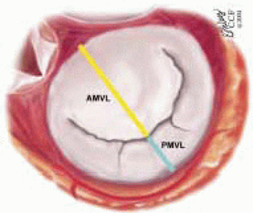
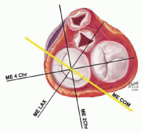
FIGURE 28.12. The line of coaptation between the two leaflets is semicircular, and the orientation of the commissure determines the segments of the valve leaflets that are visualized in the standard imaging planes.


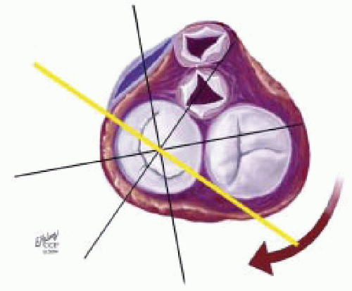
FIGURE 28.13. There is a range of mitral commissural shapes and orientations due to variation in annular size and rotation of the heart. This may be caused by individual variations and/or by enlargement of chambers that rotate the orientation of the commissure. Because of the fibrous skeleton, the rotation between the mitral valve and aortic valve is consistent.


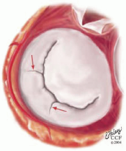
FIGURE 28.14. The posterior MV leaflet consists of three scallops that are separated by prominently distinct indentations called clefts (→). These scallops are referred to as the (antero) lateral, middle, and (postero) medial. The (antero) lateral scallop is closest to the left atrial appendage. The anterior leaflet, for purely descriptive purposes, is segmented into the corresponding lateral, middle, and medial thirds.


Papillary Muscles

Originating from the anterolateral and posteromedial walls of the left ventricle, (between the middle and apical segments), are the two papillary muscles named due to their segmental ventricular origin, anterolateral papillary (ALPM) and posteromedial papillary muscles (PMPM) (41,42,43,49). These papillary muscles run parallel to the adjacent ventricular wall. The larger ALPM usually has one or two heads, whereas the smaller PLPM may have two or three. Chordal tendons from the head of each papillary muscle attach to both of the MV leaflets. The chordae that arise from the anterolateral PM extend to the anterolateral halves of the posterior and anterior MV leaflets (Fig. 28.17). Consequently the ALPM and PMPM subtend and support their respective commissure (49). The ALPM muscle is perfused by blood from the left anterior descending coronary artery and circumflex, whereas the PMPM is supplied by a posterior descending branch from a right dominant RCA or left dominant circumflex coronary artery (51). Consequently, isolated papillary muscle infarct or rupture of the posteromedial papillary muscle is more common than a rupture of the anterolateral papillary muscle.


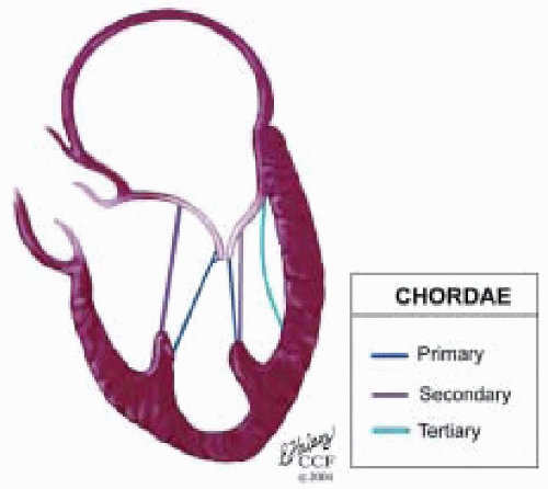
FIGURE 28.15. Chordae are fibrous tendon-like attachments extending from the leaflet to the papillary muscles and posterior ventricular wall. During systole, the papillary muscles contract and keep the chordae taut, thereby preventing prolapse of the leaflets into the left atrium. Tandler and Quain classified chordae as first, second, and third order. The first order attach to the leaflet edges adjacent to the commissure. Secondary rough zone chordae insert 8 mm from the free margin. There are two dominant secondary chordae (strut or stay chordae) going to the medial and lateral halves of the AMVL. Third order basal chordae only extend to the base of the PMVL. And maintain annular ventricular relation during the cardiac cycle.


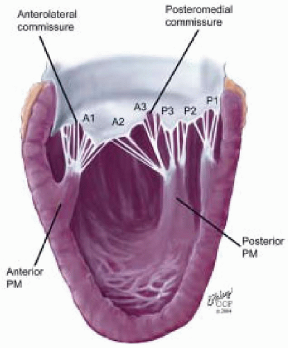
FIGURE 28.16. Originating from the anterolateral and posteromedial walls of the left ventricle (between the middle and apical segments) are the two papillary muscles called by their segmental ventricular origin: anterolateral papillary muscle (ALPM) and posteromedial papillary muscle (PMPM). These papillary muscles run parallel to the adjacent ventricular wall. The larger ALPM usually has one or two heads whereas the smaller PLPM may have two or three. Chordal tendons from the head of each papillary muscle attach to both of the MV leaflets. The chordae that arise from the anterolateral PM extend to the lateral halves of the posterior and anterior MV leaflets. Consequently the ALPM and PMPM subtend and support their respective commissure (49).


Left Ventricle

The anterolateral and posteromedial papillary muscles are inserted into the anterolateral and posteroinferior
segments of the left ventricle in the region near the interface between the middle and apical thirds of the ventricular chamber (41,44,51). The mechanical tensor function of the MVAp is maintained through the continuity that the ventricular walls provide in connecting the papillary muscles with the MV annulus (41). If there is scarring in the anterolateral or posteromedial free walls of the left ventricle, this may result in traction on the MV annulus and deformity throughout the cardiac cycle. This may lead to restriction of the PMVL during systole, with a resulting override of the AMVL and a posteriorly directed regurgitant jet.


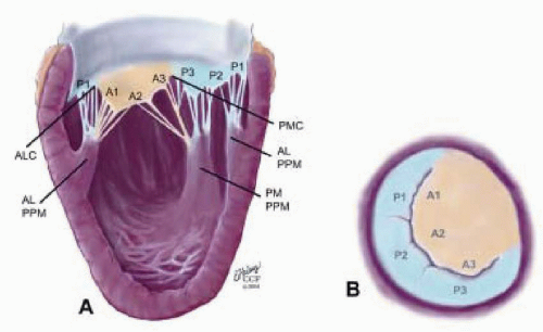
FIGURE 28.17. Originating from the anterolateral and posteromedial walls of the left ventricle (between the middle and apical segments) are the two papillary muscles called by their segmental ventricular origin: anterolateral papillary muscle (ALPM) and posteromedial papillary muscle (PMPM). These papillary muscles run parallel to the adjacent ventricular wall. The larger ALPM usually has one or two heads, whereas the smaller PLPM may have two or three. Chordal tendons from the head of each papillary muscle attach to both of the MV leaflets. The chordae that arise from the anterolateral PM extend to the lateral halves of the posterior and anterior MV leaflets. Consequently the ALPM and PMPM subtend and support their respective commissure.


Nomenclature of the Mitral Valve Apparatus (MVAp)

There are three segmental nomenclatures commonly employed to describe the anatomy of the MVAp: the ASE-SCA (Carpentier), the anatomic, and the Duran (Fig. 28.18). The American Society of Echocardiography (ASE) Nomenclature and Standards Committee and the Society of Cardiovascular Anesthesiologists (SCA) adopted the Carpentier system for standardizing the segmental leaflet nomenclature (52). The Duran nomenclature system is an extremely valuable contribution to our understanding of the MVAp because it is established on the chordal distribution between the papillary muscles and the valve leaflet segments (43).

The ASE-SCA nomenclature (Carpentier) defines the three scallops of the posterior leaflet as P1 (lateral), P2 (middle), and P3 (medial) (Figs. 28.18 and 28.19). The P1 (lateral) scallop is adjacent to the anterolateral commissure and is closest to the left atrial appendage. The P3 scallop is adjacent to the posteromedial commissure (52). This nomenclature defines the three corresponding areas of the anterior leaflet and A1 (opposite P1), A2 (opposite P2), and A3 (opposite P3).

With the anatomic nomenclature (Fig. 28.18), the posterior leaflet consists of three scallops: lateral (antero), middle, and medial (postero) as described above (52). The (antero) lateral scallop is closest to the left atrial appendage. The anterior leaflet, for purely descriptive purposes, is divided into the corresponding lateral, middle, and medial thirds. The anterolateral papillary muscle provides chordae to the lateral halves of the AMVL and PMVL (53). Consequently, the middle scallop of the posterior leaflet and middle segment of the anterior leaflet receive chordae from both papillary muscles (Figs. 28.17, 28.18 and 28.19).

The Duran nomenclature system is based on the chordal distribution and refers to the three scallops of the
posterior leaflet as P1 (lateral and closest to the left atrial appendage), PM (middle), and P2 (medial and adjacent to the posteromedial commissure) (Figs. 28.17, 28.18, 28.19 and 28.20) (53). The middle scallop (PM) is further subdivided into the PM1 and PM2, corresponding to the portion of the middle scallop that receives chordae from the anterolateral (M1) and posteromedial (M2) papillary muscles. The anterior leaflet is divided into two areas, A1 and A2, corresponding to the areas subtended by the corresponding chordal attachments from the anterolateral (M1) and posteromedial (M2) papillary muscles (53). In addition, the two commissural areas of the valve are defined as C1 (anterolateral, between A1 and P1) and C2 (posteromedial, between A2 and P2).


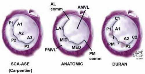
FIGURE 28.18. There are three segmental nomenclatures used to describe the anatomy of the MV apparatus: the ASE-SCA (Carpentier adoption), the anatomic, and the Duran. The American Society of Echocardiography (ASE) Nomenclature and Standards Committee of the ASE and the Society of Cardiovascular Anesthesiologists (SCA) adopted the Carpentier system for standardizing the segmental leaflet nomenclature. The Duran nomenclature is an extremely valuable contribution to our understanding of the MV apparatus because it is established on the chordal distribution between the papillary muscles and the valve leaflet segments.

SCA-ASE standardized nomenclature: P = PMVL segments (P1 = lateral scallop, P2 = middle scallop, P3 = medial scallop). A = AMVL segments (A1 = lateral segment, A2 = middle segment, A3 = medial segment). Chordae, commissures use anatomic descriptors (PMPM = posteromedial papillary muscle, ALPM = anterolateral papillary muscle)

Duran nomenclature: P = PMVL [(P1 = lateral scallop, PM = middle scallop, PM1 = lateral portion of middle scallop receiving chordae from ALPM (M1), PM2 = medial portion of middle scallop receiving chordae from PMPM (M2)]. The ALC is referred to as C1 and the PMC is C2.


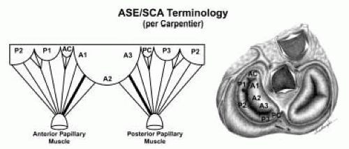
FIGURE 28.19. The SCA-ASE nomenclature (Carpentier) defines the three scallops of the posterior leaflet as P1 (lateral), P2 (middle), and P3 (medial). The P1 (lateral) scallop is adjacent to the anterolateral commissure and is closest to the left atrial appendage. The P3 scallop is adjacent to the posteromedial commissure. This nomenclature defines the three corresponding areas of the anterior leaflet and A1 (opposite P1), A2 (opposite P2), and A3 (opposite P3). Originating from the anterolateral and posteromedial walls of the left ventricle (between the middle and apical segments) are the two papillary muscles called by their segmental ventricular origin, anterolateral papillary muscle (ALPM) and posteromedial papillary muscle (PMPM). These papillary muscles run parallel to the adjacent ventricular wall. The larger ALPM usually has one or two heads, whereas the smaller PLPM may have two or three. Chordal tendons from the head of each papillary muscle attach to both of the MV leaflets. The chordae that arise from the anterolateral PM extend to the lateral halves of the posterior and anterior MV leaflets. The ALPM and PMPM subtend and support their respective commissure (49).


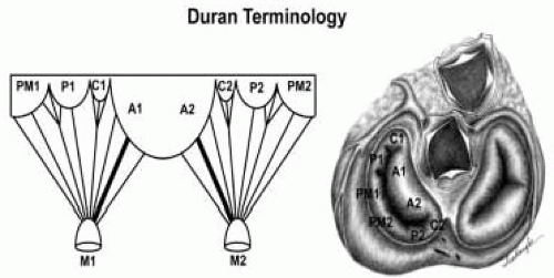
FIGURE 28.20. The Duran nomenclature system is based on the chordal distribution and refers to the three scallops of the posterior leaflet as P1 (lateral and closest to the left atrial appendage), PM (middle), and P2 (medial and adjacent to the posteromedial commissure) (53). The middle scallop (PM) is further subdivided into the PM1 and PM2, corresponding to the portion of the middle scallop that receives chordae from the anterolateral (M1) and posteromedial (M2) papillary muscles. The anterior leaflet is divided into two areas, A1 and A2, corresponding to the areas subtended by the corresponding chordal attachments from the anterolateral (M1) and posteromedial (M2) papillary muscles. In addition, the two commissural areas of the valve are defined as C1 (anterolateral, between A1 and P1) and C2 (posteromedial, between A2 and P2).


CORRELATION WITH IMAGING PLANES

The goal of the two-dimensional echocardiographic exam of the MVAp is to develop a three-dimensional understanding of the anatomy of the dysfunctional MV . While this may be routinely accomplished with three-dimensional transesophageal echocardiography in the future (Fig. 28.21), such an understanding is routinely available through a cognitive reconstruction of three-dimensional anatomy utilizing multiplane two-dimensional TEE imaging. The posterior and superior location of the midesophagus in relation to the adjacent blood-filled left atrium and MV annulus enable detailed 360° imaging of the MV leaflets and apparatus utilizing a two-dimensional multiplane transducer (Fig. 28.22). If the rotational axis of the transducer is positioned in the center of the AMVL, it enables up to 360° imaging of the MV leaflets and an understanding of the three-dimensional structure of the MVAp (Fig. 28.23).


FIGURE 28.21. Three-dimensional visualization of a severe prolapse of the PMVL (red →) performed by TEE in the cardiac operating room. Calcified A2 of the AMVL (green →) and aortic valve are noted.


FIGURE 28.22. The posterior and superior location of the midesophagus in relation to the adjacent blood-filled left atrium and MV annulus enable ideal detailed 360° imaging of the MV leaflets and apparatus utilizing a two-dimensional multiplane transducer.


FIGURE 28.23. If the rotational axis of the transducer is positioned in the center of the anterior mitral valve leaflet (AMVL), it enables 360° imaging of the MV leaflets and an understanding of the 3-dimensional structure of the MV apparatus.

The MV may be examined utilizing up to 10 or more variations of 6 of the recommended ASE-SCA imaging planes frequently used in evaluating the MVAp (Table 28.2 A-J). These include the midesophageal four-chamber (ME 4 Chr MV), midesophageal commissural (ME Com MV), midesophageal two-chamber (ME 2 Chr MV), midesophageal LAX (ME LAX MV), transgastric short-axis (TG SAX MV), and transgastric two-chamber (TG 2 Chr MV) planes. These image planes are obtained by manipulations of the TEE probe including advancing or withdrawing, turning right (clockwise) and left (counterclockwise), rotating the transducer angulations forward or backward, and flexing the probe to the right or left (Fig. 28.24). For an expanded description of the probe manipulations for each of the standard imaging planes and their variations, please see the section on “Comprehensive Examination in MV Surgery” or Chapter 6, “Comprehensive and Abbreviated Intraoperative TEE Examination.”

The following section lists the standard imaging planes and their variations in the sequence in which they are commonly utilized in the evaluation of the MVAp. The probe manipulation required to obtain an image plane, which is a variation of the “ASE-SCA recommended cross-sectional view,” is included with the description of the visualized MV anatomy (52). The anatomic description for these imaging planes is always dependent on the three-dimensional orientation of the line of coaptation and the extent of probe manipulation.


Midesophageal Four-Chamber MV and Variations

Midesophageal Five-Chamber MV (ME 5 Chr MV) Lower-Esophageal Four-Chamber MV (LE Four Chr MV) (Table 28.2 A-C, Figs. 28.25, 28.26, 28.27 and 28.55)


Midesophageal Four-Chamber MV (ME 4 Chr MV)

Transducer Depth: 30 cm

Transducer Rotation: 0°-15°

Depending on the orientation of the MV commissure and transducer rotation angle, the 2-D plane may cut through the A2 and P2 and/or P1 segments of the MV. On the monitor in this imaging plane, the anterior leaflet is displayed on the left and the posterior leaflet on the right. Proceeding from left to right are A2, midcommissure, and P2 and/or P1.


Midesophageal Five-Chamber MV (ME 5 Chr MV)

Variation of ME 4 Chr MV

Transducer Depth: 30 cm


Probe Manipulation: Withdraw from ME 4 Chr MV

This imaging plane cuts through the left ventricular outflow tract. Depending on the orientation of the MV commissure and transducer rotation angle, the 2-D plane may cut through the A1 segment, anterolateral commissure, and P1 segments of the MV. On the monitor in this imaging plane, the anterior leaflet is displayed on the left and the posterior leaflet on the right. Proceeding from left to right are A1, anterolateral commissure, and P1.


Lower-Esophageal Four-Chamber MV (LE Four Chr MV)

Variation of ME 4 Chr

Transducer Depth: 32 cm

Probe Manipulation: Advance

Depending on the orientation of the MV commissure and transducer rotation angle, the 2-D plane may cut through the A3 segment, posteromedial commissure, and the P3 scallop of the MV. On the monitor in this imaging plane, the anterior leaflet is displayed on the left and the posterior leaflet on the right. Proceeding from left to right are A3, posteromedial commissure, and P3.


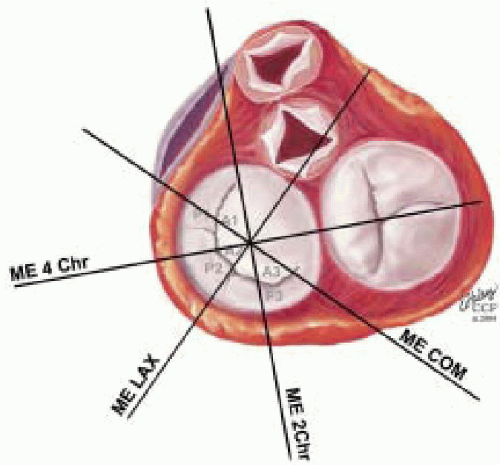
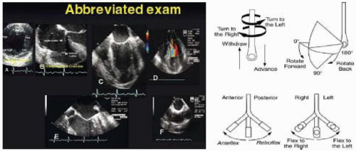
FIGURE 28.24. Standard image planes and their variations are obtained by manipulations of the TEE probe, including advancing or withdrawing, turning right (clockwise) and left (counterclockwise), rotating the transducer angulations forward or back, and flexing the probe to the right or left.


Midesophageal Commissural MV and Variations


Midesophageal Commissural Right MV (Table 28.2E and Fig. 28.29)


Midesophageal Commissural Left MV (Table 28.2F and Fig. 28.30) (Table 28.2D-F, Figs. 28.28, 28.29, 28.30 and 28.47)


Midesophageal Commissural MV (ME Com MV) (Table 28.2D and Fig. 28.28)

Transducer Depth: 30 cm

Transducer Rotation: 45°-70°


TABLE 28.2. Correlation of Image Plane and Cardiac Anatomy


Imaging Plane Nomenclature


Probe Depth


Transducer Angle


Probe Maneuver


3D Imaging Plane View


2D Anatomic Imaging Plane


Corrresponding Segmental Anatomy


ME 5 Chr MV


28 cm


0-15°


Withdraw


image


image


image


ME 4 Chr MV


30 cm


0-15°


Probe Insertion


image


image


image


LE 4 Chr MV


30 cm


0-15°


Advance


image


image


image


ME Com MV


30 cm


45-70°


Rotate Transducer Angle Forward


image


image


image


ME Com Right MV


30 cm


45-70°


Turn Right (Clockwise)


image


image


image


ME Com Left MV


30 cm


45-70°


Turn Left (Counter-Clockwise)


image


image


image


ME 2 Chr MV


30 cm


80-110°


Rotate Transducer Angle Forward


image


image


image


ME LAX MV


30 cm


110-150°


Rotate Transducer Angle Forward


image


image


image


TG SAXB


35 cm


0-5°


Advance probe Rotate Transducer Angle Forward


image


image


image


TG 2 Chr


35 cm


70-90°


Rotate Transducer Angle Forward


image


image


image


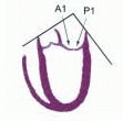
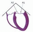
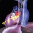
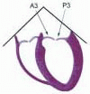
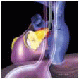
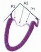
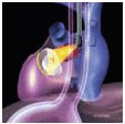
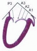
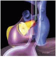
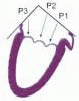
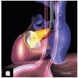
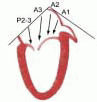
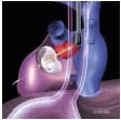
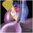
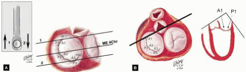
FIGURE 28.25 A and B. Midesophageal Five Chamber MV (ME 5 Chr MV). Variation of ME 4 Chr MV; Transducer Depth: 30 cm; Probe Manipulation: Withdraw from ME 4 Chr MV. A: The TEE probe is slowly withdrawn 1-2 cm from the ME 4 Chr imaging plane to obtain the ME 5 Chr view. The LE 4 Chr imaging plane is obtained by advancing the probe 1-2 cm from the ME 4 Chr plane. B: This imaging plane cuts through the left ventricular outflow tract. Depending on the orientation of the MV commissure and transducer rotation angle, the 2-D plane may pass through the A1 segment, anterolateral commissure, and P1 segments of the MV.


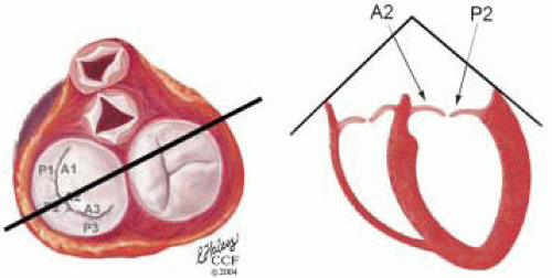
FIGURE 28.26. Four Chamber MV (LE Four Chr MV). Variation of ME 4 Chr transducer; Depth: 32 cm; Probe Manipulation: Advance depending on the orientation of the MV commissure and transducer rotation angle. The 2-D plane may pass through the A2 segment, middle commissure, and the P2 scallop of the MV. The height of the P2 and A2 may be measured in this plane for comparison with the ME LAX MV measurements.


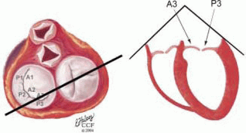
FIGURE 28.27. Lower-esophageal Four Chamber MV (LE Four Chr MV). Variation of ME 4 Chr transducer; Depth: 32 cm; Probe Manipulation: Advance depending on the orientation of the MV commissure and transducer rotation angle. The 2-D plane may pass through the A3 segment, posteromedial commissure, and the P3 scallop of the MV.


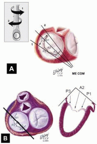
FIGURE 28.28. Midesophageal Commissural MV (ME Com MV). Transducer Depth: 30 cm: Transducer Rotation 45-70° A: The ME Com MV is obtained by rotating the transducer forward to 45-70°. Turning the probe to the right (clockwise) and to the left (counterclockwise) enable visualization of the variations of this imaging plane. B: Depending on the orientation of the MV commissure and transducer rotation angle, the 2-D plane may cut through the P3 scallop, the posteromedial commissure, tip of A2, anterolateral commissure, and the P1 segments of the MV.

Depending on the orientation of the MV commissure and transducer rotation angle, the 2-D plane may cut through the P3 scallop, the posteromedial commissure, tip of A2, anterolateral commissure, and the P1 segments of the MV. On the monitor (from left to right) are P3, posteromedial commissure, A2, anterolateral commissure, and P1. The annular plane drawn between the MV annulus on the left of the screen and the MV annulus on the right usually represents the most inferior (closest to the apex) aspects of the saddle-shaped annulus. A plane drawn between these points consequently may overcall MV prolapse.


Midesophageal Commissural Right MV (ME ComR MV) (Table 28.2E and Fig. 28.29)

Variation of ME Com MV

Transducer Depth: 30 cm


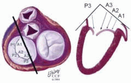
FIGURE 28.29. Midesophageal Commissural Right MV (Probe Turned Right) (ME ComR MV). Variation of ME Com; Transducer Depth: 30 cm; Probe Manipulation: Turn left or counterclockwise; Transducer Rotation: 45-70°. Depending on the orientation of the MV commissure and transducer rotation angle, the 2-D plane may pass through the P3, A3, A2, and A1 segments.

Transducer Rotation: 45°-70°

Probe Manipulation: Turn right or clockwise

Depending on the orientation of the MV commissure and transducer rotation angle, the 2-D plane may cut through the P3 scallop, the posteromedial commissure, the A3 segment, the A2 segment, and the A1 segment. On the monitor (proceeding from left to right) are P3, the posteromedial commissure, A3, A2, and A1.


Midesophageal Commissural Left MV (ME ComL MV) (Table 28.2F and Fig. 28.30)

Variation of ME Com

Transducer Depth: 30 cm

Transducer Rotation: 45°-70°


FIGURE 28.30. Midesophageal Commissural Left MV (Probe Turned Left) (ME ComL MV): Variation of ME Com; Transducer Depth: 30 cm; Probe Manipulation: Turn left or counterclockwise; Transducer Rotation: 45-70°. Depending on the orientation of the MV commissure and transducer rotation angle, the 2-D plane may pass through the P3, P2, and P1 scallops.


Probe Manipulation: Turn left or counterclockwise Depending on the orientation of the MV commissure and transducer rotation angle, the 2-D plane may cut through the P3, P2, and P1 scallops. The commissure may not be visualized except during diastole. On the monitor (proceeding from left to right) are P3, P2, and P1.


Midesophageal Two-Chamber MV and Variations (ME 2 Chr MV) (Table 28.2G, Figs. 28.31, 28.32, 28.33 and 28.48)

Midesophageal Two-Chamber Right MV

Midesophageal Two-Chamber Left MV

Midesophageal Two-Chamber MV (ME 2 Chr MV)

Transducer Depth: 30 cm

Transducer Rotation: 80°-110°

Probe Manipulation: Midline

Depending on the orientation of the MV commissure and transducer rotation angle, the 2-D plane may cut through the P3 scallop, the posteromedial commissure, and the A3, A2, and A1 segments. On the monitor (proceeding from left to right) are P3, posteromedial commissure, A3, A2, and A1.


Midesophageal Two-Chamber Right MV (ME 2 ChrR MV) (Fig. 28.32)

Variation of ME 2 Chr MV

Transducer Depth: 30 cm

Transducer Rotation: (80°-110°)

Probe Manipulation: Turn right (clockwise)

Depending on the orientation of the MV commissure and transducer rotation angle, the 2-D plane may cut through the P3 scallop, the apex of the posteromedial commissure, the A3 segment, and the base of the A2 segment. On the monitor (proceeding from left to right) are P3, posteromedial commissure, A3, and A2.


Midesophageal Two-Chamber Left MV (ME 2 ChrL MV) (Fig. 28.33)

Variation of ME 2 Chr MV

Transducer Depth: 30 cm

Transducer Rotation: 80°-110°

Probe Manipulation: Turn left or counterclockwise Depending on the orientation of the MV commissure and transducer rotation angle, the 2-D plane may cut through the P3, P2, and P1 scallops. The commissure may not be visualized except during diastole. On the monitor (proceeding from left to right) are P3, P2, and P1.


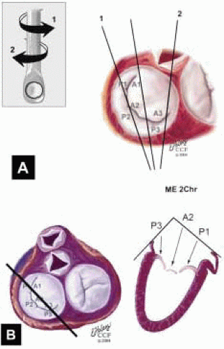
FIGURE 28.31. Midesophageal Two Chamber MV (ME 2 Chr MV). Transducer Depth: 30 cm; Probe Manipulation: Midline; Transducer Rotation: 80-110°. A: The ME 2 Chr imaging plane is obtained by rotating the transducer forward to 80-110°. Variations of this plan are obtained by turning the probe to the right and left. B: Depending on the orientation of the MV commissure and transducer rotation angle, the 2-D plane may cut through the P3 scallop, the posteromedial commissure, the A3 segment, the A2 segment, and the A1 segment.


Midesophageal Long-Axis MV and Variations (Table 28.2H, Figs. 28.34, 28.35, 28.36 and 28.49)

Midesophageal Long-Axis Right MV

Midesophageal Long-Axis Left MV

Midesophageal Long-Axis MV (ME LAX MV) (Table 28.2H, Fig. 28.34)

Transducer Depth: 30 cm

Transducer Rotation: 110°-150°

Depending on the orientation of the MV commissure and transducer rotation angle, the 2-D plane passes through the minor axis of the MV annulus and aortic valve. The 2-D
plane may cut through the P2 scallop, the midcommissure, and through the A2 segment. On the monitor (proceeding from left to right) are P2, the midcommissure, and the A2 segment of the MV. The aortic valve is seen of the right of the screen. The MV annulus to the left of the screen and to the right—adjacent to the aortic valve—are the most superior (farthest from the apex) aspects of the annulus. A plane drawn between these points provides a more specific reference for diagnosing MV prolapse.


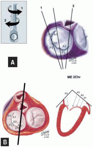
FIGURE 28.32. Midesophageal Two Chamber Right MV (Turned Right) (ME 2 ChrR MV). Variation of ME 2 Chr MV; Transducer Depth: 30 cm; Transducer Rotation: 80-110°; Probe Manipulation: Turn right (clockwise). Depending on the orientation of the MV commissure and transducer rotation angle, the 2-D plane may cut through the P3 scallop, the apex of the posteromedial commissure, the A3 segment, and base of the A2 segment.


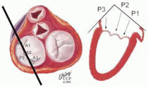
FIGURE 28.33. Midesophageal Two Chamber Left MV (Turned Left) (ME 2 ChrL MV). Variation of ME 2 Chr MV; Transducer Depth: 30 cm. Probe Manipulation: Turn left or counterclockwise; Transducer Rotation: 80-110°. Depending on the orientation of the MV commissure and transducer rotation angle, the 2-D plane may cut through the P3, P2, and P1 scallops. The commissure may not be visualized except during diastole.


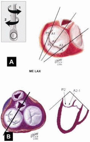
FIGURE 28.34. Midesophageal Long Axis MV (ME LAX MV). Transducer Depth: 30 cm; Transducer Rotation: 110-150°. A: The ME LAX MV imaging plane is obtained by rotating the transducer forward to 110-150°. Variations of this plan are obtained by turning the probe to the right and left. B: Depending on the orientation of the MV commissure and transducer rotation angle, the 2-D plane passes through the minor axis of the MV annulus and aortic valve. The 2-D plane may cut through the P2 scallop, the midcommissure, and through the A2 segment. Height of the PMVL, AMVL, and C-sept are measured in this plane and compared to the ME 4 Chr MV measurements. This plane demonstrates the most superior aspects of the MV annulus.


Midesophageal Long-Axis Right MV (ME LAXR MV) (Fig. 28.35)

Variation ME LAX MV

Transducer Depth: 30 cm

Transducer Rotation: 110°-150°

Probe Manipulation: Turn right or clockwise Depending on the orientation of the MV commissure, transducer rotation angle, and extent of probe manipulation, the 2-D plane may cut through the P2 scallop, the posteromedial commissure, and the P3 scallop. The commissure may not be visualized except during diastole. On the monitor (proceeding from left to right) are P2, possibly the posteromedial commissure, and P1.


Midesophageal Long-Axis Left MV (ME LAXL MV) (Fig. 28.36)

Variation ME LAX MV

Transducer Depth: 30 cm


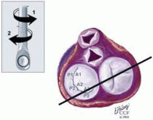
FIGURE 28.35. Midesophageal Long-Axis Right MV (Probe Turned Right) MV ME LAXR MV. Variation ME LAX MV; Transducer Depth: 30 cm; Probe Manipulation: Turn right clockwise; Transducer Rotation: 110-150°. Depending on the orientation of the MV commissure, transducer rotation angle, and extent of probe manipulation, the 2-D plane may cut through the P2 scallop, the posteromedial commissure, and P3 scallops. The commissure may not be visualized except during diastole.


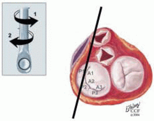
FIGURE 28.36. Midesophageal Long-Axis Left MV (ME LAXL MV). Variation ME LAX MV; Transducer Depth: 30 cm Probe Manipulation: Turn left or counterclockwise; Transducer Rotation; 110-150°. Depending on the orientation of the MV commissure, transducer rotation angle, and extent of probe manipulation, the 2-D plane may cut through the P2 scallop, the anterolateral commissure, and P1 scallops. The commissure may not be visualized except during diastole.

Transducer Rotation: 110°-150°

Probe Manipulation: Turn left or counterclockwise

Depending on the orientation of the MV commissure, transducer rotation angle, and extent of probe manipulation, the 2-D plane may cut through the P2 scallop, the anterolateral commissure, and the P1 scallop. The commissure may not be visualized except during diastole. On the monitor (proceeding from left to right) are P2, possibly the anterolateral commissure, and P1.


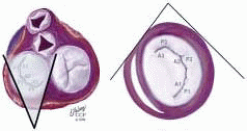
FIGURE 28.37. Transgastric Basal Short Axis (TG SAXB). Transducer Depth: 35 cm; Transducer Rotation: 0-5°. In this imaging plane, the AMVL (A1-2-3, bottom to top) is visualized on the left and the PMVL (P1-2-3, bottom to top) is visualized on the right. The clear space to the left of the AMVL edge and toward the bottom of the screen is the left ventricular outflow tract (LVOT), which is shaded in gray. Systolic turbulence in this area suggest SAM with LVOTO.


Transgastric Basal Short Axis (TG SAXB) (Table 28.2I and Fig. 28.37)

Transducer Depth: 35 cm

Transducer Rotation: 0°-5°

In this imaging plane, the AMVL (A1-2-3, bottom to top) is visualized on the left and the PMVL (P1-2-3, bottom to top) is visualized on the right. The clear space to the left of the AMVL edge and toward the bottom of the screen is the left ventricular outflow tract (LVOT).


Transgastric Two Chamber (TG 2 Chr) (Table 28.2J and Fig. 28.38)

Transducer Depth: 35 cm

Transducer Rotation: 70°-90°

This image is similar to the ME 2 Chr imaging plane except that the ventricle is horizontally oriented. Depending on the orientation of the MV commissure and transducer rotation angle, the 2-D plane may cut through the P3 scallop, the posteromedial commissure, and the A3, A2, and A1 segments. On the monitor (proceeding from top to bottom) are P3, posteromedial commissure, A3, A2, and A1.


Intraoperative Examination Approach


Principles of Intraoperative Examination (Table 28.3)

The principles of the intraoperative echocardiographic (IOE) examination for patients undergoing MV surgery are guided by the unique demands of the cardiac surgery environment. By the very nature of this atmosphere, the IOE exam is performed in a sequence that first resolves the issues guiding patient management. Yet it also acknowledges the more comprehensive aspects of active patient management and the need to provide digitally archived documentation of the patient’s complete examination for future comparison. While these may appear to be conflicting objectives, eventually every echocardiographer incorporates both into the daily routine of an efficiently organized IOE exam with which they feel comfortable. To accomplish these goals (Table 28.4), the systematic IOE exam may be structured into a priority ordered exam and a more general comprehensive exam (54). To prevent significant midexam revelations from occurring and reordering priorities, the priority ordered exam is initiated by a brief abbreviated overview exam followed by the more complete focused diagnostic exam. In addition to the diagnostic issues that are already on the agenda, the abbreviated overview exam provides an up-to-date assessment of additional issues that must be addressed. It also recognizes the important role of IOE in the ongoing management of the patient and, if necessary, permits the immediate adjustment of the patient’s hemodynamic management while the remainder of the IOE exam takes place.


TABLE 28.3. Principles of Intraoperative Echo Exam in Mitral Valve Surgery


1.


Addresses Critical Issues of MV Surgery (Table 28.1)


2.


Systematic Examination


Organized by priority


Initial overview exam (patient management and exam organization)


Focused diagnostic exam ( priority issues)


Comprehensive exam documented


3.


Efficient (critical issues and comprehensive exam in prebypass period)


4.


Severity by Weighted Integration 2-D Imaging and Doppler


5.


Study Results Discussed with Surgeon and Documented in Record


6.


Comprehensive Digital Study Achieved


7.


Compares Results with Pre-OR Data and Addresses Variances


Variance explained to extent possible


Communicated with surgical team


Communicated with patient’s primary physician


8.


IOE Exam under CQI Process


9.


Training and Hospital Credentialing of Qualified Personnel


10.


Equipment Maintained and Updated


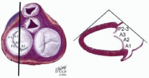
FIGURE 28.38. Transgastric Two Chamber (TG 2 Chr). Transducer Depth: 35 cm; Transducer Rotation 70-90°. This image is similar to the ME 2 Chr imaging plane except that the ventricle is horizontally oriented. Depending on the orientation of the MV commissure and transducer rotation angle, the 2-D plane may cut through the P3 scallop, the posteromedial commissure, the A3 segment, the A2 segment, and the A1 segment.


TABLE 28.4. Systematic Intraoperative Echo Exam in MV Surgery


Systematic IOE Exam Components


Priority Ordered Examination


Abbreviated overview examination


Rapid assessment of cardiac function (patient management)


Diagnostic screen for organizing focused study


Focused diagnostic examinaion


General comprehensive examination


Remaining ASE-SCA


Stages of IOE Exam in MV Surgery


Precardiopulmonary bypass (pre-CPB)


Postcardiopulmonary bypass (post-CPB)


Preseparation CPB (predep CPB)


Postseparation CPB (post- CPB)


To ensure that the examination is conducted efficiently, the methods that are used in assessing the severity of MV dysfunction are those that are more easily performed in a multitasking environment. As recommended by the ASE Nomenclature and Standards Committee and Task Force on Valvular Regurgitation, the assessment of the severity of MV dysfunction and its secondary pathophysiology integrates both the structural and Doppler parameters of severity weighted by the quality of data obtained and quantitative reliability (35). Severity is graded as mild, moderate, and severe, using terms such as “mild-to-moderate” or “moderate-to-severe” to characterize intermediate levels of severity (35). The term trace regurgitation is used to describe that which is barely detected. For mitral stenosis (MS), the terms mild, moderate, and severe are also used.

Subdued lighting (reduced monitor glare) and periods without electrocautery interference during critical portions of the intraoperative exam contribute to collecting quality 2-D images and Doppler-derived hemodynamic data. Such an atmosphere permits the precise recognition of intricate structural abnormalities (vegetation, thrombi, right-to-left shunts) that may have potentially devastating consequences if missed. It also enables the acquisition of the quality of diagnostic information that may confidently guide the pivotal surgical and hemodynamic decisions.

For organization purposes, the examination may be structured into two distinct phases: precardiopulmonary bypass (pre-CPB) and postcardiopulmonary bypass (post-CPB). The post-CPB incorporates an abbreviated preseparation bypass (pre-Sep CPB) exam. Each of the phases has critical issues that are addressed during the progression of the procedure (Tables 28.5 and 28.6). For patients undergoing MV surgery, a priority directed exam may be performed at each of these phases of the surgical procedure. If the patient encounters hemodynamic instability at any point during the course of the procedure, an abbreviated overview exam is performed followed by a more focused diagnostic exam directed by the clinical course or as revealed during the abbreviated overview exam. If the patient’s course is not entirely smooth, an examination following chest closure may direct clinical intervention or provide assurance.

For each stage of the surgical procedure, the abbreviated overview exam is followed by the focused diagnostic exam in addressing those issues that pertain to that stage of the surgery (Table 28.4). When the critical issues have been resolved and corresponding images stored digitally, the general comprehensive examination is completed by filling in any portions that were not performed during the focused diagnostic portion of the exam.


TABLE 28.5. The Precardiopulmonary Bypass (Pre-CPB) Exam


1.


Confirm and Refine Preoperative Assessment


Confirm MV dysfunction and severity


Determine repairability of valve


Refine pathoanatomy and mechanism


Explain variances


2.


Determine the Need for Unplanned Surgical Intervention


Secondary pathophysiology


LV dysfunction


Increased LA or LAA thrombi


Pulmonary hypertension


RV dysfunction


Tricuspid regurgitation


Right to left shunt (PFO, ASD)


Hepatic congestion


Associated abnormality


Associated congenital anomalies


Cleft MV and primum ASD


Similar pathologic process


Ventricular dysfunction


Valve dysfunction


Acquired: rheumatic valve


Degenerative: myxomatous or calcific disease


Endocarditis


Vascular disorder


Unrelated process


Primary aortic valve stenosis or regurgitation


3.


Cannulation and Perfusion Strategy


4.


Addresses Surgical Procedure-Specific Issues


5.


Predict Complications


Inability to repair


Documented risks


SAM and LVOTO: PMVL height, C-sept distance


Dilated annulus, MACa++, >3 segments


Central MR jet


Rheumatic


Multiple mechanisms of valve dysfunction


Myxomatous and ischemic


Mitral stenosis


Endocarditis involving fibrous skeleton or annulus


Endocarditis


LVOT obstruction (MVRep or MVR)


Mitral annular calcification


Pseudoaneurysm


Perivalvular regurgitation


Ventricular dysfucntion


Coagulopathy (hepatic congestion)


The conclusions of the systematic examination at the pre-CPB and post-CPB are communicated directly with the surgical team in addition to being documented in the patient’s permanent medical record. The digital loops and images, which support the diagnostic conclusions and
constitute the complete systematic examination, are achieved for future retrieval for comparison and reviewed under an organized CQI process as recommended by the Intraoperative Council of the American Society of Echocardiography (29).


TABLE 28.6A. Preseparation (Pre-Sep Examination


Abbreviated Preseparation Exam


Abbreviated assessment of cardiovascular function


Cardiac performance


Initial screen for complications


Cannulation and perfusion-related


Check for dissection or intramural hematoma


Pre-CPB protruding plaques still present?


Procedure-related complications


New or secondary pathophysiology


Initial assessment of MV surgery


Persistent MR or residual or new MS


Significant procedure-related complications (not improved by time)


Suture dehiscence


Leaflet damage


Pseudoaneurysm (slide-related)


MV stenosis


Pseudoaneurysm


Left circumflex obstruction


Latrogenic Shunt: ASD, aorta to LA fistula


SAM and LVOT obstruction


Significant perivalvular regurgitation


Mechanical leaflet malfunction


LVOT strut obstruction


Midventricular disruption


Ring dehisence


Significant perivalvular fistula


LA avulsion


Monitor micro-air clearance


Assess ventricular function and optimal


Time for separation CPB


Secondary pathophysiology


Pulmonary hypertension


RV dysfunction or TR


Complications of cannulation and perfusion


Aortic dissection or intramural hematoma


Micro-air or atheromatous emboli


Myocardial ischemia


Intraoperative Echocardiography (IOE) Examination and Outcomes


Precardiopulmonary Bypass (Pre-CPB IOE)


Critical Issues of the Pre-CPB Exam (Table 28.5)

For patients with MV dysfunction, a decision to proceed with surgical intervention is one that has been established on the progression of the patient’s clinical symptomatology and objective assessment of the severity of primary MV dysfunction and its secondary effects (20). Consequently, the pre-CPB exam is to verify the need for surgery and to focus on better understanding the underlying pathologic changes of the structural anatomy of the MVAp and the mechanism of MV dysfunction in addition to resolving other critical issues that are addressed in this phase.


TABLE 28.6B. Postseparation (Post-Sep) CPB Exam


Assess cardiovascular function


Diagnose complications and mechanisms


MV repair


Incomplete repair


Primary mechanism


Residual prolapse


Residual annular dilatation


Secondary mechanisms


Repaired P2 with type IIIb (asymmetric)


New ischemic MR


Commissural regurgitation


Technique-related


Suture dehiscence


Interscallop malcoaptation


Overshortening leaflet


Leaflet damage


Pseudoaneurysm (slide-related)


MV stenosis


Pseudoaneurysm


Aortic valve incompetence


Circumflex coronary obstruction


Latrogenic shunt: ASD, aorta to LA fistula


SAM and LVOT obstruction


MV replacement


Perivalvular regurgitation


Mechanical leaflet malfunction


LVOT strut obstruction


Midventricular disruption


Ring dehiscence


Both MVRep and MVR


Perivalvular fistula


Pseudoaneurysm


LA avulsion


Assess ventricular function


Secondary pathophysiology


Pulmonary hypertension


RV dysfunction


Complications of cannulation and perfusion


Aortic dissection or intramural hematoma


Micro-air emboli


Segmental ischemia


CNS dysfunction


Emboli (atheroma-related)


Infarcted or ischemic intestine


Stroke


Renal infarct


Determining the severity of MV dysfunction is accomplished by the weighted integration methods of determining severity of valve dysfunction, incorporating the two-dimensional echocardiographic and Doppler exams (35,55,56). Detection of the severity of MR relies on established Doppler parameters, including color flow (CF) Doppler maximum jet area (CF Doppler MJA) mapping, CF Doppler vena contracta (VC) diameter (57,58,59), pulsed wave (PW) Doppler interrogation of the pulmonary veins (57,60,61,62), and proximal flow convergence (PFC) determination of the “peak” regurgitant orifice area (ROA) (63,64,65,66). Should there be significant discrepancies, more extensive volumetric quantitative techniques are used. Following surgical repair of the MV, the initial post-CPB exam is pivotal for long-term patient outcome. An incorrect assessment may unnecessarily return the patient to CPB for further repair or an unnecessary MVR exposing the patient to a lifetime of anticoagulation and all the risks associated with prosthetic valves. Inaccuracy may be introduced into this crucial decision-making period by suboptimal technical settings (CF Doppler gain, scale, wall filter, power, depth with lowered pulse repetition frequency, and frequency) or relying on CF Doppler alone for determining the severity of MR. Given the potential eccentricity of regurgitant jets following attempted valve repair, the potential for inherent inaccuracies with the various techniques come into focus. Utilizing more quantitative assessment methods (vena contracta, PFC, ROA), which are specifically suited for the character of the regurgitant jet (Table 28.12), provides a solid foundation for such important decisions that may significantly impact the patient’s outcome and daily routine. A mutual understanding of these essential issues occurs outside of the operating room and permits time for hemodynamic equilibration and the efficient assessment of the surgical results using simplified quantitative parameters. MR jets, which are brief but of a significant size (by CF Doppler MJA), should be weighted for their duration. CF Doppler M-mode (color m-mode) enables an accurate visualization of the jet duration and depth of penetration (Fig. 28.39). If the severe jet is short-lived despite having a MJA of > 6 cm2 (Nyquist 50 cm/sec-60 cm/sec), it may not be indicative of significant mitral regurgitant (67). Before returning to CPB and re-repair or MVR with greater than mild to moderate MR, a quantitative method of severity assessment (ROA, vena contracta) will improve the patient’s long-term management (Fig. 28.39).

Assessment of MS similarly incorporates two-dimensional imaging and Doppler. The 2-D qualitative assessment incorporates a functional assessment of the MV apparatus utilizing the splitability index planimetery from the basal TG SAX imaging plane and (55, 68,69,70). As with the assessment of MR, CF Doppler provides a reliable screening assessment (71). Visualizing transmitral diastolic proximal flow convergence directs the exam to more quantitative methods of assessment. Use of PISA proximal flow convergence has been validated for determining the severity of MS. If the stenosis is subvalvular, it is inherently inaccurate. MVA in Doppler assessment of MS incorporates aspects of both CW and PW Doppler in providing a semiquantitative and quantitative assessment of the MV area. By determining how rapidly the transvalvular pressure equilibrates between the LA and LV equilibrate the MV area may be the pressure half time and decelerating time methods (68,69,70,71). Except for circumstances of aortic regurgitation and issues of variance in assumptions for LA and LV compliance, these methods have proven reliable. The continuity equation incorporates both PW and CW Doppler techniques and is reasonably reliable as long as the reference valve is not regurgitant (55).

Determination of the mechanism of MV dysfunction for both MR and MS is assessed using a combination of 2-D echocardiography (annular size, segmental systolic and diastolic valve leaflet motion, and leaflet coaptation) and correlation with the corresponding color flow Doppler characterization of systolic regurgitant jet direction and/or diastolic flow disturbance visualized in the same imaging plane (29). In determining the mechanism of MR or MS, color flow Doppler is an essential component of the evaluation. With the surgical team understanding the etiology and mechanism of dysfunction, the feasibility of a successful valve repair or alternative replacement is better understood. The mechanism and underlying pathologic process directly affect the patient’s long-term prognosis (29,53,55,56,74).

Other issues resolved by the pre-CPB exam include:

1. Evaluating the presence and severity of significant secondary or coexisting cardiovascular disease that would alter the patient’s surgical management

2. Establishing the optimal cannulation-perfusion and myocardial protection strategy

3. Assessing cardiac function in determining the optimal intraoperative hemodynamic management of the patient

4. Assessing the probability for potential post-CPB complications related to the patient’s MV surgery or use of cardiopulmonary bypass (aortic regurgitation, aortic dissection, and intramural hematoma).

The assessment of secondary physiology focuses on determining the presence of an increased LA pressure, pulmonary hypertension, secondary RV dysfunction with dilatation, and/or lateral enlargement of the tricuspid annulus. With MV dysfunction there may be increased of left atrial pressure with chronic dilatation of the chamber. In acute MR, the LA does not dilate and the LA pressures are elevated more acutely with the onset of pulmonary congestion and hypertension. Utilizing PWD interrogation
of the pulmonary vein, the LAP may be estimated. If there is blunting of the S wave in all pulmonary veins, an elevation of LAP (> 15 mm Hg) is usually present (55,56,57). In chronic MR, the left atrium may dilate to greater than 70 mm (56,57). With persistent elevations of LAP, the patient may develop fixed pulmonary hypertension with RV dysfunction, eventually causing RV dilatation, and lateral enlargement of the tricuspid annulus, leading to tricuspid regurgitation in up to 25% of patients having MV surgery (75). The RAP may be elevated leading to chronic hepatic congestion (diagnosed by a lack of respiratory variation in hepatic vein diameter) and in the present right-to-left shunting patent foramen ovale.


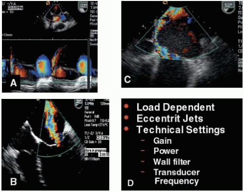
FIGURE 28.39A, B, C, and D. A: The post-CPB TEE exam following MVRep may reveal short duration MR jets with a significant maximum jet area. The color m-mode clarifies the duration of the jet. B: Color flow Doppler is a good screening technique to distinguish the presence of severe or mild MR. Eccentric jets will lead to an underestimation of MV severity due to the wall hugging (Coanda effect). D: Due to the many factors influencing the jet area size (frequency, wall filter, gain, Nyquist limit, PRF, sector depth, and loading conditions), quantitative methods (including PISA ROA, and vena contracta) should be used to distinguish intermediate grades (mild to moderate, moderate, and moderate to severe). However, color flow Doppler is an essential component of the exam in determining mechanism of MR.

Notwithstanding the many valuable and recognized contributions that IOE has made to the patient undergoing valvular heart surgery, the ability to identify patients who are at a higher risk for postoperative stroke and neurocognitive dysfunction continues to have a daily impact on the management of these patients. This is not only a devastating complication that impacts patient morbidity
and mortality, but it significantly increases the costs associated with valvular heart surgery. The cannulation and perfusion strategy is directed by the IOE assessment of the proximal ascending and descending aorta. Epiaortic scanning is performed if

1. Protruding plaques are seen in the descending aorta

2. Plaques are palpated at the anticipated site of cannulation or cross clamping

3. The patient has significant risk factors for aortic atheroma (103)

Significant aortic regurgitation may identify patients at risk for ventricular distension or ineffective antegrade cardioplegia administration, which may direct an alternative protection strategy, such as direct interostial administration of antegrade cardioplegia or more heavily weighted dependence on retrograde cardioplegia administration. As the cross clamp is released prior to reinstitution of a rhythm, cardiac distension may indicate the need for an AV vent through the pulmonary vein (76).


The Pre-CPB IOE Exam and Outcome Studies (Table 28.5)

Intraoperative echocardiography (IOE) has been effectively utilized in guiding MVRep surgery since it was initially reported in 1986, using epicardial imaging with color flow Doppler determination of the mechanism of dysfunction (8). Not only has the IOE exam helped the individual patient, but it has also shortened the learning curves of cardiac surgeons and served as a catalyst to hasten the evolutionary development of MVRep. In 1998, Gillinov and colleagues reported on 1,072 patients who had successful MVRep surgery performed between 1985 and 1997 (77). The study included a subset of patients who had not received IOE guidance. In comparing those patients who received IOE compared with those who did not, the long-term durability was 98% compared to 92% (77). Following the initial surgical procedure, there was a preponderance of late failures that occurred within the first year (Figs. 28.40 and 28.41).

The potential repairability of the valve is an issue that affects the immediate management of the patient and impacts long-term outcome. Understanding the importance of the technical capabilities and experience of the surgeon and the perioperative team, the feasibility of MV repair is determined by the pathologic process and the mechanism and severity of dysfunction. It is the correlation of the direct surgical examination of the components of the valve apparatus with the real-time pre-CPB IOE exam of the same structures and determination of mechanisms of dysfunction, which yields a coordinated surgical strategy that will effectively navigate through those issues impacting the immediate and long-term outcome of the patient (Table 28.5).


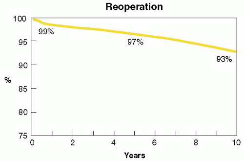
FIGURE 28.40A. Of 1,072 patients undergoing successful MV repair between 1985 and 1997, the long-term durability at 10 years was 93%.


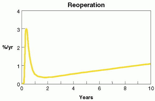
FIGURE 28.40B. Hazard curves for reoperation following successful MV repair. Though reoperations are an infrequent event, the first year is time of highest incidence.


New Clinical Information

The pre-CPB IOE exam provides incremental information that impacts the surgical management of patients undergoing MV surgery. Michel-Cherqui et al. reported the results of 203 consecutive cardiac surgery patients and found a 17% incidence of IOE changing the preoperative diagnosis (78). Chaliki et al. found a 12% incidence of new findings influencing the intraoperative management of their patients (38). Lytle et al. reported that IOE discovered previously undiagnosed MV dysfunction requiring MVRep in 5% of 82 consecutive higher risk patients undergoing myocardial revascularization (18).


Determine Mechanism and Probability of Repair

The IOE exam provides the surgeon with information that enables a more directed inspection of the mitral apparatus.
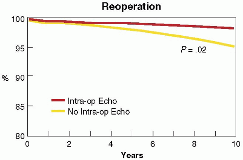
In 1992, Stewart et al. reported the Cleveland Clinic’s initial experience with 286 patients undergoing MVRep (79). In those patients who received IOE guidance, the surgical diagnosis of mechanism and location was compared with the results of the pre-CPB exam. The IOE exam diagnosed the localized mechanisms most accurately with posterior-leaflet prolapse or flail (93%), anterior-leaflet prolapse or flail (94%), and restricted leaflet motion or rheumatic thickening (91%). It correctly diagnosed papillary muscle elongation or rupture in 75%, ventricular and annular dilatation in 72%, leaflet perforation in 62%, and bileaflet prolapse or flail in 44%. Of the 5% of patients who had more than one mechanism, the IOE was only able to diagnose both mechanisms in 38%, and one of the two mechanisms in 92%. Overall, the accuracy for diagnosing mechanisms was 85% (33). In a similar study, Foster et al. reported the high accuracy of utilizing a more regimented systematic IOE exam, reporting agreement between the TEE and surgical localizations of mechanisms in 96% of native MV segments or scallops (224 of 234 segments or scallops, p < 0.0001) and 88% of perivalvular prosthetic regurgitant segments (p < 0.001) (80). Lambert et al. reported on the ability of a consistent systematic examination to accurately determine the location and mechanism of MV dysfunction (compared with surgical inspection) in 96% compared with 70% in an IOE exam that was not systematically performed (81). Omran et al. prospectively evaluated 170 consecutive patients undergoing MVRep with a systematic segmental examination of the MVAp. They found that IOE accurately identified abnormal segments in 90 to 97% of patients (82). Segments that were most accurately identified as abnormal were P2 (97%) and least accurately identified were A3 (90%). The accuracy of correctly localizing to AMVL and PMVL was 95% and 100%, respectively (82). In 1999, Caldarera et al. discovered that IOE provided accurate anatomic measurements of the anteroposterior diameter of the mitral annulus compared with surgical inspection (83). A measured diameter > 35 mm in the ME 4 Chr imaging plane was indicative of annular dilatation at the time of surgery requiring annuloplasty. In 1999, Enriquez-Sarano et al. compared the ability of IOE to accurately diagnose the etiology and mechanism of MV dysfunction in patients undergoing MVRep surgery with TTE (29). They found that IOE provided a superior ability to diagnose the correct etiology (99% vs. 95%) and mechanism of dysfunction (99% vs. 94%). The IOE exam was also more accurate in diagnosing MV prolapse (99% vs. 95%) and flail segments (99% vs. 83%, p < 0.001). The IOE exam was able to predict, on the basis of accurately diagnosing etiology and mechanism, those patients who were most likely to have a successful MVRep (p < 0.001) and a higher 5-year survival (p < .001) (29). Similar studies have consistently demonstrated the diagnostic capabilities of the IOE exam to accurately provide the surgical team with the information that will enable them to correlate their surgical findings in determining the optimal surgical strategy for repair or replacement of the valve.


FIGURE 28.41. The patients who did not have intraoperative echo had a trend for lower long-term durability (92%) compared to those who received intraoperative guidance with TEE and /or epicardial echo (98%, p < 0.02) (77).


Variances with Preoperative Severity MV Dysfunction

Despite numerous reports demonstrating the ability to accurately determine the underlying anatomy and mechanism of dysfunction, there have been recognized discrepancies between the preoperative (both TEE and TTE) and intraoperative assessment of severity in some patients. Grewal et al. compared preoperative TEE with the IOE exam performed under general anesthesia to determine the unloading effect on the severity of MR. The severity of MR was assessed using color flow Doppler (CFD), maximal jet area (MJA), and vena contracta jet diameter (VCJD) (84). They found 22 of the 43 patients (51%) improved by at least one MR severity grade when assessed under general anesthesia. They found the most significant changes occurred in patients with functional MR, with normal MV leaflets (84). However, patients with structural leaflet dysfunction (flail) demonstrated little if any change in the MR severity. Bach et al. also compared the severity of preoperative TEE with the IOE using similar parameters of severity assessment (85). They determined that patients with structural valve leaflet abnormalities (flail) did not have a significant change in their severity assessment whereas those with functional MR decreased significantly in patients with functional MR (p < 0.001) (85).

In a report of 1,265 patients undergoing MV surgery in 1999, Chaliki et al. reported a total of 96 patients in whom the pre-CPB found no significant structural or functional abnormality of the mitral apparatus (38).
Based on this finding the decision was made not to surgically inspect the valve in 95 of these patients. In patients with ischemic MR undergoing myocardial revascularization, Cohn et al. reported on patients undergoing myocardial revascularization with moderate preoperative MR; 90% of these patients were downgraded to 0-2+ by the IOE exam (19). Seven of the patients went from moderate MR to no MR intraoperatively and did not receive a MVRep or MVR. Postoperatively, 3 out of 7 patients returned to their original 3+ MR, and 4 returned to 2+ MR on their postoperative TTE (19).

All of these studies have made remarkable contributions to our understanding of the variances that we have observed in patients with “nonstructural” functional MR. Clearly, when MR is recorded an accompanying BP or other relevant information would enable a clearer understanding of the issue as it presents.

When explaining variances between the preoperative assessment and the intraoperative exam, as Thomas and many others have taught us, there are physical principles of ultrasound which we use daily that contribute to the variance in our intraoperative assessment (29,57). As explained in Chapter 1, the size of the maximum CF Doppler jet area (MJA) is determined by a number of considerations, including the regurgitant orifice area and the systolic LV-LA gradient accelerating the velocity and producing momentum (a product of velocity × flow rate and the most significant determinate of jet size), which is related to momentum (flow rate × velocity). Other factors include the eccentricity of the regurgitant jet (leads to wall constraint), and settings used on the ultrasound platform (power, transducer receiver gain, frequency of transducer—higher frequency transducer causes greater Doppler shift, wall filter, PRF, color scale or Nyquist limit, and size of scan sector—affecting pulse repetition frequency). Because of the closer proximity of the TEE transducer to the heart, higher frequencies can be used, causing a more pronounced jet area because of the relative lack of tissue attenuation at the imaging distance for TEE. By having the CF Doppler scale higher than what may have been used in the preoperative assessment, the MJA will be comparatively reduced.

From a clinical perspective, if the variance in the OR is more than two grades less, the possibility always exists that the patient may have had indolent ischemia at the time of the original exam. In these circumstances, if canceling the MV procedure is a consideration, altering the loading conditions with neosynephrine or challenging with a bolus of intravenous fluid may duplicate the MV dysfunction seen preoperatively. It is always a good idea to consult other colleagues who may provide insight into the patient’s clinical course or more quantitative methods that may not be utilized on a routine basis in an intraoperative practice (18,62,63).

In MV disease that chronically elevates the pulmonary artery pressures, leading to RV dysfunction and dilatation, the tricuspid annulus will dilate laterally adjacent to the posterior tricuspid leaflet. The need for tricuspid valve repair in patients undergoing MV surgery is reported to be approximately 25% and is indicated in the presence of > moderate TR (75). Almost all of these procedures are tricuspid valve repairs.


Predict Complications

In an era of minimally invasive and other cutting edge approaches to MV disease, the potential for difficulties keeps everyone vigilant. Such challenges do not become complications unless they remain undetected and adversely affect the patient. IOE clearly provides a safety net mechanism, enabling us to identify problems at a time when they may be more readily corrected. The pre-CPB has also been used to anticipate complications following MVRep and MVR (Table 28.5). Such complications are directly related to the surgical procedure, the patient’s underlying disease process, or the use of cardiopulmonary bypass. Unsuccessful MVRep is classified as either immediate or late. Late failures occur after the patient’s initial OR experience. Causes of immediate failure may be secondary to an extensively diseased valve, calcification, segmental involvement making the valve more difficult to repair, systolic anterior motion (SAM) of the MV with associated LVOT obstruction (LVOTO), suture dehiscence, development of ischemic MR, and incomplete repair second mechanism. Many of these causes may be detected by the pre-CPB IOE with a prediction of the difficulty of repair, raising the index of suspicion during the post pump evaluation. Marwick et al. reported on the factors associated with immediate failure during the initial MVRep procedure (86). Of 26 patients requiring second CPB runs for persistent MV, the causes were determined to be LVOT obstruction (38%), suture dehiscence (23%), and “incomplete repair” (38%) (86). Agricola et al. reported on 255 consecutive patients undergoing MVRep for MR receiving a quadrilateral resection (87). Twenty-one patients had significant residual MR related to:

1. Residual cleft, provoking interscallop malcoaptation

2. Residual prolapse of the anterior or posterior leaflets

3. Residual annular dilation

4. Left ventricular outflow obstruction

5. Suture dehiscence (64)

Omran et al. evaluated 170 consecutive patients undergoing MV repair, with 9% of patients receiving an MVR due to persistent significant MR (82). Using univariant and multivariant analysis, predictors of unsuccessful repair (or predicting the need for MV replacement) were:


1. MV annulus > 5.0 cm

2. MAC

3. Central MR jet

4. ≥ 3 segments/scallops with prolapse or flail

By allocating one point for each of these factors, if the score was 0, 1, or > 1 the observed risk was 0%, 10%, and 36% (82).


Systolic Anterior Motion (SAM) with LVOT Obstruction (LVOTO)

Systolic anterior motion (SAM) with LVOT obstruction (LVOTO) and an associated posteriorly directed jet has been reported in up to 16% of patients undergoing MVRep for myxomatous MV dysfunction (86,88,89). More recent experiences place the incidence under 1%-2% of MVReps (37). When SAM with LVOTO occurs, inotropic agents and vasodilators (including vasodilating inhalation agents) should be discontinued to evaluate unprovoked mechanism of MR. If the administration of volume and pressor agents does not reverse the process, further repair may be required with a sliding annuloplasty, which reduces the height of the PMVL. In 1988, Schiavone et al. reported a small series of 12 patients with postrepair SAM and LVOT obstruction with a rigid ring (88). Of those patients who left the OR with persistent SAM and LVOTO, the severity of LVOTO had, in fact, diminished in follow-up at 27 months. However, when provoked with amyl nitrate, a significant gradient returned and was associated with significant MR (88). Lee et al. reported on a similar group of 14 patients, developing postrepair SAM and LVOT obstruction (89). They determined that these patients had common features of reduced pre-CPB coaptation to septal (C-sept) distances (2.65 cm) and PMVL systolic heights of 1.9 cm (Figs. 28.41A and 28.41B) (Fig. 28.43) (89). By effectively moving the coaptation line away from the interventricular septum, Carpentier developed of the sliding annuloplasty in 1988 as a potential solution to this issues (90). Cosgrove et al. reported that sliding annuloplasty is performed on patients with a PMVL height of > 1.5 cm (Fig. 28.44) (91,92). Maslow et al. evaluated patients undergoing MV repair for myxomatous MV disease in attempting to identify echocardiographic predictors of LVOTO associated with SAM of the MV (93). Using intraoperative TEE and the ME 4 Chr imaging plane, the lengths of the coapted AMVL and PMVL leaflets, the distance from the coaptation point to the septum (C-Sept), annular diameters, and left ventricular internal diameter (LVID) at end systole were measured in 33 patients undergoing MV repair. Eleven patients developed significant SAM with LVOT obstruction and had smaller AL/PL ratios (0.99 vs. 1.95, p < 0.0001) and C-Sept distances (2.53 vs. 3.01 cm,
p = 0.012) prior to pre-CPB compared to those who did not develop LVOT obstruction with SAM (93). These findings were consistent with studies demonstrating that SAM with LVOT obstruction following MVRep surgery is associated with anterior malposition of the point of coaptation. This study lends further support to the strategy of the sliding annuloplasty to prevent post-MVRep LVOTO (90,91,92). From these studies the predictive indicators of post-MVRep SAM with LVOTO would be a AMVL: PMVL ratio less than 1.0, PMVL height > 1.5 cm, and a small systolic LVOT diameter (C-septal distance < 2.6 cm)
would indicate a higher risk MVRep patient population for developing post-CPB SAM and LVOT obstruction and the potential need for a posterior MV complete or modified sliding annuloplasty.

Only gold members can continue reading. Log In or Register to continue

Stay updated, free articles. Join our Telegram channel

Jul 15, 2016 | Posted by in CARDIOLOGY | Comments Off on Assessment in Mitral Valve Surgery

Full access? Get Clinical Tree

Get Clinical Tree app for offline access