Assessment in Cardiac Intervention
Ivan P Casserly
E. Murat Tuzcu
Patrick L. Whitow
Mario Garcia
Robert M. Savage
Although many challenges remain in the field of percutaneous coronary intervention (PCI), the lessons learned over the last three decades have generally made these procedures very safe. More than one million PCIs are performed annually in the United States. During this time, noncoronary cardiac intervention in adult patients was restricted largely to the treatment of aortic, mitral, and pulmonic stenosis, using balloon valvuloplasty techniques. However, over the last 10 years, the field of noncoronary cardiac intervention has rapidly evolved and its scope has extended well beyond the treatment of stenotic valves.
There is no doubt that the dominant force behind these new developments is the proliferation of new technologies. In concert with these developments has come the realization that surgical therapies can be replaced by effective endovascular alternatives. In fact, a number of the newer endovascular technologies have been initiated by cardiothoracic surgeons, seeking to replicate their surgical techniques, using endovascular devices. This burgeoning field presents a tremendous opportunity to offer novel and alternative therapies, but significant challenges, too. Compared with coronary artery disease, the disease states being treated during noncoronary cardiac intervention vary significantly, which necessitates a multidisciplinary approach to patient management. Another challenge is the requirement for high quality echocardiographic imaging during preprocedural evaluation, the procedure itself (Table 37.1), and the postprocedural management of these patients. Although the development of intracardiac echocardiography (ICE) has provided some autonomy for the interventionalist during some procedures, a successful noncoronary cardiac intervention program cannot be built without the support and expertise offered by our echocardiographer colleagues.
In this chapter, the principle noncoronary cardiac interventions that are currently performed by adult cardiac interventionalists requiring echocardiographic guidance are described. Some of these are well-established techniques with good clinical data supporting their efficacy. Others are at an early stage of development and, while holding great promise, further study is required before they can gain widespread acceptance.
PERCUTANEOUS AORTIC VALVE REPLACEMENT
For patients with acquired calcific aortic stenosis, aortic valve replacement is the treatment of choice, providing effective symptomatic relief and a survival benefit (1). However, some patients are not deemed operative candidates due to the presence of serious comorbid conditions that predict high operative mortality. The introduction of percutaneous balloon aortic valvuloplasty (PBAV) in the mid-1980s offered a new therapeutic option for these patients. While the short-term outcomes of PBAV were encouraging, long-term follow-up demonstrated near 100% restenosis
rates at 2 years (2). PBAV is currently used only to provide palliation or to serve as a bridge toward aortic valve replacement. The limitation of PBAV has provided the impetus to develop percutaneous aortic valve replacement techniques for the treatment of patients with severe aortic stenosis not amenable to surgical valve replacement.
rates at 2 years (2). PBAV is currently used only to provide palliation or to serve as a bridge toward aortic valve replacement. The limitation of PBAV has provided the impetus to develop percutaneous aortic valve replacement techniques for the treatment of patients with severe aortic stenosis not amenable to surgical valve replacement.
TABLE 37.1. Utility of Various Echocardiographic Imaging Modalities During Noncoronary Cardiac Intervention | |||||||||||||||||||||||||||||||||||||||||||||||||||||||||||||||||
|---|---|---|---|---|---|---|---|---|---|---|---|---|---|---|---|---|---|---|---|---|---|---|---|---|---|---|---|---|---|---|---|---|---|---|---|---|---|---|---|---|---|---|---|---|---|---|---|---|---|---|---|---|---|---|---|---|---|---|---|---|---|---|---|---|---|
| |||||||||||||||||||||||||||||||||||||||||||||||||||||||||||||||||
Following ex-vivo and animal testing of a variety of valve bioprostheses and techniques, Cribier et al., performed the first percutaneous transcatheter implantation of an aortic valve prosthesis (Percutaneous Valve Technologies, Inc., Fort Lee, NJ) in April 2002 (3). The valve consists of three bovine (subsequently changed to equine) pericardial leaflets that are sutured to a stainless steel stent frame (14 mm long, 21-23 mm diameter) (Figure 37.1a), which in turn is mounted on a commercially available Z-MED II (NuMED, Inc., Hopkintonm NY, USA; 30mm long, 23 mm diameter) balloon valvuloplasty catheter (Fig. 37.1b). In brief, the prosthesis is introduced over a continuous wire loop (360 cm stiff guidewire) extending from the femoral vein to the right atrium, across the septum into the left atrium, mitral valve, left ventricle, aorta, and femoral artery. To prepare for valve placement, BAV is performed (23 mm balloon). Currently, a 24Fr sheath in the femoral vein is required to allow delivery of the aortic valve prosthesis, which is positioned at the midsection of the native aortic valve, using the valvular calcifications as a marker. Rapid and full inflation of the balloon followed by rapid deflation results in delivery of the valve prosthesis (Fig. 37.2). To date, a total of 14 such procedures have been performed in 12 patients with functional class IV symptoms and two patients with cardiogenic shock (unpublished data). Successful implantation of the prosthesis was achieved in 12 patients (86%). Successful implantation is associated with an impressive reduction of the mean aortic gradient (44 ± 13 to 5 ± 0.5 mmHg) and increase in aortic valve area (0.5 ± 0.1 to 1.7 ± 0.1 cm2). There was one procedural death, and four late noncardiac deaths. The latter finding is not surprising given the clinical context in which device implantation is performed in these patients.
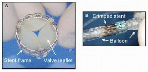 FIGURE 37.1. A: Appearance of prosthetic aortic heart valve when expanded. Valve consists of three leaflets attached to a metal stent. B: Appearance of valve when crimped onto balloon for delivery into patient via femoral sheath. Reproduced with permission from Eltchaninoff H et al., J Interv Cardiol 2003;16(6):515-21. |
All of these procedures are performed under TEE guidance, and both TTE and TEE are essential in the accurate follow-up of these patients. During the procedure, TEE is most helpful in assessing outcome following implantation of the prosthesis. TEE allows measurement of the stent diameter, which should be between 21 and 23 mm, and assessment of stent geometry, which should ideally be circular. TEE is also helpful in assessing paravalvular regurgitation, which reflects failure of apposition of the prosthesis with the native calcific valve. Severe paravalvular regurgitation (≥ +3) was present in one- third of patients immediately following placement of the aortic prosthesis. Follow-up TEE and TTE allow assessment of the prosthetic leaflets, valvular and paravalvular regurgitation, planimetry of the aortic valve area, aortic valve gradients, and left ventricular function.
MITRAL VALVE REPAIR
Percutaneous catheter-based approaches to the management of functional and structural mitral regurgitation (MR) in human subjects are at an early stage of development but represent a potentially dramatic advance (5). Functional MR has a complicated pathogenesis, but is felt to result from mitral annular dilatation and altered ventricular geometry, which causes incomplete leaflet coaptation. The resultant mitral regurgitation begets further LV dysfunction and mitral annular dilatation, setting up a vicious perpetuating spiral of progressive mitral regurgitation and left ventricular failure. Surgical repair generally involves a ring- or suture-based mitral annuloplasty, which reshapes the annulus and promotes leaflet coaptation. Several groups have attempted to mimic this strategy, using percutaneous methods by exploiting the relationship of the coronary sinus and great cardiac vein with
the posterior aspect of the mitral annulus (Fig. 37.3). Although different types of device are in development (CCure, ev3/Mitralife, Santa Rosa, CA, USA; Viacor, Inc., Wilmington, MA), in essence, they each consist of a metal constraint device that is inserted into the coronary sinus, using the internal jugular venous access site. The goal is to apply tension on the underlying annulus, resulting in a ˜25¶ reduction in annular diameter. TEE guidance during the procedure is essential to monitoring the annular diameter and the associated change in mitral regurgitation. Published data has been limited to small animal studies, where insertion of the device was associated with an impressive reduction in mitral annular diameter (4.17 ± 0.14 to 3.24 ± 0.11 cm) and severity of mitral regurgitation, and a consistent improvement in hemodynamic assessments (cardiac output, pulmonary capillary wedge pressure) (6). While this therapy is promising, both short-and long-term clinical data are required. The complexity of functional MR mandates a clear demonstration of efficacy in human subjects before acceptance of the technique. Additionally, a number of safety concerns exist including coronary sinus perforation and thrombosis, coronary ischemia secondary to impingement on the circumflex artery, and arrhythmias. These complications were not seen in the early human experience of a group in Venezuela, but given the small sample size, caution is still warranted (unpublished data).
the posterior aspect of the mitral annulus (Fig. 37.3). Although different types of device are in development (CCure, ev3/Mitralife, Santa Rosa, CA, USA; Viacor, Inc., Wilmington, MA), in essence, they each consist of a metal constraint device that is inserted into the coronary sinus, using the internal jugular venous access site. The goal is to apply tension on the underlying annulus, resulting in a ˜25¶ reduction in annular diameter. TEE guidance during the procedure is essential to monitoring the annular diameter and the associated change in mitral regurgitation. Published data has been limited to small animal studies, where insertion of the device was associated with an impressive reduction in mitral annular diameter (4.17 ± 0.14 to 3.24 ± 0.11 cm) and severity of mitral regurgitation, and a consistent improvement in hemodynamic assessments (cardiac output, pulmonary capillary wedge pressure) (6). While this therapy is promising, both short-and long-term clinical data are required. The complexity of functional MR mandates a clear demonstration of efficacy in human subjects before acceptance of the technique. Additionally, a number of safety concerns exist including coronary sinus perforation and thrombosis, coronary ischemia secondary to impingement on the circumflex artery, and arrhythmias. These complications were not seen in the early human experience of a group in Venezuela, but given the small sample size, caution is still warranted (unpublished data).
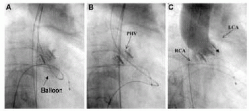 FIGURE 37.2. A: The prosthetic aortic valve is deployed by inflation of the 23 mm balloon on which the stent valve is delivered. B: Appearance of prosthetic valve following deployment. C: Aortography following placement of prosthetic aortic valve demonstrating patent right and left coronary arteries above the prosthesis. Reproduced with permission from Cribier A et al. Circulation 2002;106:3006-8. |
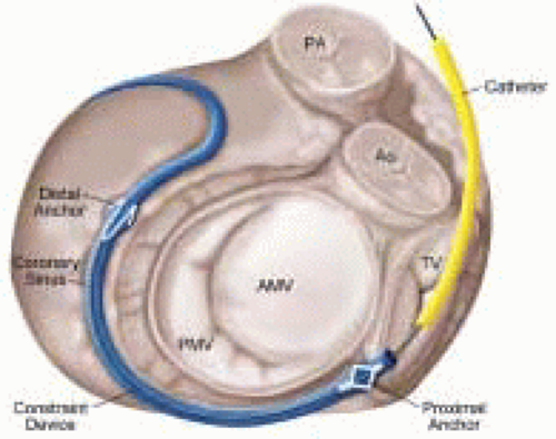 FIGURE 37.3. Schematic of percutaneous mitral annular reduction technique for treatment of functional mitral regurgitation. A metal constraint device is positioned in coronary sinus opposite the posterior aspect of the mitral valve. |
Structural MR is caused by pathology of the valve leaflets or supporting structures (i.e., chordae, papillary muscles). Since the early 1990s, Alfieri has championed the double-orifice technique of surgical mitral repair for more complicated cases of structural mitral regurgitation with excellent clinical outcomes (7). Most commonly, the technique involves suturing the middle scallops of the anterior and posterior mitral leaflets, and is used to treat bileaflet or anterior leaflet prolapse (7). In a further imitation of a surgical technique, St. Goar et al., has reported an endovascular edge-to-edge technique using a V-shaped, polyester-covered metal clip for repair of structural MR (Evalve, Inc., Redwood City, CA) (Fig. 37.4) (8). The procedure is outlined in Figs. 37.5 and 37.6. In summary, using the femoral venous access site, and transseptal puncture, a steerable guiding catheter is placed in the left atrium above the mitral valve. The V clip is attached to the delivery catheter, then advanced through the guide and opened in the left atrium. The opened clip crosses the mitral valve perpendicular to the line of leaflet coaptation and in the same vertical plane as the middle scallops of the anterior and posterior leaflets. Once in the left ventricle and below the free edges of the leaflets, the clip is retracted and the leaflets grasped. A thorough 2-D and color Doppler echocardiographic assessment is performed to confirm adequate placement with complete or near-complete elimination of mitral regurgitation. If device placement is unsatisfactory, the device may be released and redeployed until successful placement is achieved. The importance of TEE guidance during each step of this procedure cannot be overemphasized (Fig. 37.6).
Published data with this device is only available from animal studies but is encouraging (8). To date, the device has been placed in eight human subjects, with an effective reduction of MR in six, and no major adverse clinical events (unpublished data). The technical expertise required by both the interventionalist and echocardiographer for this procedure is significantly greater than that for the mitral annular reduction technique. Clearly, this technique is in its infancy, and a much larger body of safety and efficacy data is required before the technique can be applied in clinical practice. It is likely that the ultimate success of percutaneous treatments for structural MR will be determined by the ability to use endovascular techniques to treat both the structural defect and mitral annular dilatation, as currently practiced by cardiothoracic surgeons during most surgical repairs. While current technologies offer some promise toward that end, their niche will initially be restricted to nonsurgical candidates. Beyond this patient group, the burden of proof
will rest heavily on percutaneous techniques to prove their equivalency or superiority to established surgical techniques.
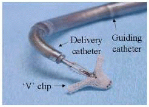 FIGURE 37.4. Polyester covered metal V-shaped clip used to perform percutaneous edge-to-edge repair of mitral valve. |
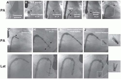 FIGURE 37.5. Fluoroscopic procedural images from patient undergoing endovascular edge-to-edge repair of mitral valve using E-valve system. A-F. Following transeptal puncture (A), a Mullins sheath is placed in the left atrium (B). A stiff guide wire is placed in the left atrium and the Mulllins sheath is exchanged for a 24 Fr guide (C-E). The device is advanced through the guide into the left atrium (G), opened (H), advanced across the mitral valve, retracted against the mitral valve, and then closed grasping the leaflets (G-I). Once adequate device placement is determined by echocardiography, the device is released (J). |
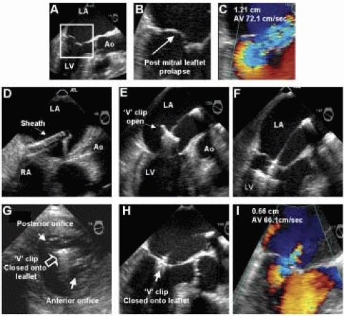 FIGURE 37.6. TEE images from same patient described in Figure 37.5. A-C: Images demonstrating prolapse of the posterior mitral leaflet and associated anteriorly directed mitral regurgitation at baseline. D: Guide catheter in left atrium. E-F: Device opened in left atrium and advanced into left ventricle. G-H: Transgastric (G) and esophageal (H) views demonstrating appearance of mitral valve, following capture of the middle scallops of the anterior and posterior mitral leaflets by the V clip. I: Color Doppler of mitral flow following device placement. |
NONSURGICAL SEPTAL REDUCTION FOR HYPERTROPHIC CARDIOMYOPATHY
Significant left ventricular outflow tract (LVOT) obstruction is present in 10% of patients with hypertrophic cardiomyopathy (HCM), and is believed to contribute significantly to symptoms of angina, dyspnea on exertion, and syncope (9). Until the early 1990s, surgical myectomy was the only therapeutic option for patients who were refractory to medical therapy. At this time, observational data regarding implantation of DDD pacemakers in these patients showed some promise, but subsequent randomized studies failed to demonstrate any objective improvement in functional status, and this therapy has largely been abandoned (10,11). In 1995, Sigwart reported a novel therapeutic approach that involved the injection of absolute alcohol into the first septal perforator branch, producing a circumscribed myocardial infarction involving the portion of septum in contact with the anterior mitral leaflet during the typical systolic anterior motion (SAM) of the leaflet observed in HCM (Fig. 37.7). 12 Clinical outcomes were impressive, and subsequent larger series, involving hundreds of patients, demonstrated an early and sustained reduction in LVOT gradient (˜90%), and resolution or effective relief of symptoms in > 90% of patients during long-term follow-up (13,14).
The majority of operators use TTE guidance for alcohol septal ablation procedures. The critical function of TTE guidance is to help select the target septal perforator, supplying the area of septum in contact with the anterior mitral leaflet during SAM. This is sometimes challenging because of the tremendous interindividual variation in the number, distribution, and overlap in distribution of the septal perforator branches. Following inflation of a balloon in the selected perforator branch, an echo contrast agent (e.g., Optison, Amersham Health, Princeton, NJ) is injected through the balloon lumen (diluted 1:8 with saline). Imaging from the apical and parasternal views allows a determination of the myocardium perfused by the septal perforator branch (Fig. 37.7D). In some patients, this procedure may have to be repeated with the balloon in various branches or sub-branches to confirm the optimal location for injection of alcohol. By more effective localization of the targeted myocardium,
the use of myocardial contract echocardiography (MCE) during alcohol ablation has been associated with improved hemodynamic results, despite a reduction in the total infarct size (13). The safety of the procedure is improved by identifying perforator branches whose perfusion distribution involves the posterior free wall and papillary muscles, making them unsuitable targets. Additionally, the incidence of complete heart block, which occurred in 20% to 40% of patients in early series, has been reduced to 5% to 10% in series using MCE guidance (15). TTE may also be used to monitor the effects of the procedure on the LVOT gradient at rest and during provocation (e.g., amyl nitrate, post-PVC), and to document the resolution or improvement in SAM and the associated posteriorly directed mitral regurgitation (Fig. 37.8). In summary, TTE and MCE make alcohol septal ablation a safer and more effective procedure. They should be regarded as mandatory components of the technique.
the use of myocardial contract echocardiography (MCE) during alcohol ablation has been associated with improved hemodynamic results, despite a reduction in the total infarct size (13). The safety of the procedure is improved by identifying perforator branches whose perfusion distribution involves the posterior free wall and papillary muscles, making them unsuitable targets. Additionally, the incidence of complete heart block, which occurred in 20% to 40% of patients in early series, has been reduced to 5% to 10% in series using MCE guidance (15). TTE may also be used to monitor the effects of the procedure on the LVOT gradient at rest and during provocation (e.g., amyl nitrate, post-PVC), and to document the resolution or improvement in SAM and the associated posteriorly directed mitral regurgitation (Fig. 37.8). In summary, TTE and MCE make alcohol septal ablation a safer and more effective procedure. They should be regarded as mandatory components of the technique.
Stay updated, free articles. Join our Telegram channel

Full access? Get Clinical Tree


