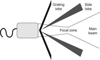
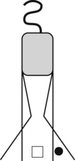
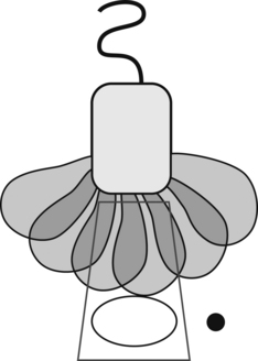
Chapter 18 Artifacts and Pitfalls Christopher J. Gallagher and Gian Paparcuri When you are in the OR, you are forever asking yourself, “Is it real, or is it Memorex?”. We get seduced by the great images, and you have to shake yourself and say, “This is not a REAL LIVE picture, this is an ULTRASOUND CREATION OF A PICTURE, and ultrasound can fool you”. Artifacts change their appearance and appear or disappear depending on the view. Real structures will remain constant and can be seen in multiple views. (See also CFD artifacts, pitfalls, and masses.) Acoustic imaging assumptions (to assign the location and intensity of received echoes): US beam exits transducer as a complex 3-D bowtie shape (below figure) with additional off-axis low-energy beams (side lobes and grating lobes). Strong reflector (highly reflective object) located outside the main US beam (peripheral field) may generate detectable echoes that will be displayed as having originated from within the main beam. Misplaced echoes overlapping anechoic structure. Adjust focal zone to the level of interest and place transducer at the center of the object of interest. Beam width: distal beam (widened beam) widens beyond the actual transducer width (below figures). If the beam is oscillating rapidly, the multiple artifactual echos produced by the side lobes are displayed as a curved line at the same level as the true object. Options: reduce power (below figures).
 Interfere with image interpretation.
 Reflections not representing true anatomy.
 Part of an image will not represent the anatomic structure (reality) accurately
 Reflections arise only from structures along the beam’s main axis. Echoes detected originated from within the main ultrasound beam. Problem: side lobes, grating lobes.
 Sound travels directly to a reflector and back (straight line). Problem: refraction.
 Echo returns to transducer after a single reflection. Problem: mirror images, reverberations.
 Sound (sound beam and its echo) travels in a straight line.
 Reflection’s intensity (strength) is related to tissue characteristics. Problem: attenuation.
 Acoustic energy in an ultrasound field is uniformly attenuated.
Artifacts
 Artifacts associated with US beam characteristics (beam width, side lobe, grating lobe, edge shadow).
Artifacts Associated with US Beam Characteristics


Artifacts and Pitfalls


