Fig. 17.1
Radiofrequency ablation procedure facilitated by TEE. Mid esophageal bicaval view with color Doppler imaging demonstrating puncture (arrow) of a Fontan baffle (F) in a patient with complex heart disease consisting of dextrocardia, double inlet left ventricle and pulmonary atresia to facilitate an electrophysiologic procedure . (A) Atrium
Valve Dilation Procedures
TEE has been utilized during valvuloplasty of stenotic valves. Although it has been applied to procedures involving all cardiac valves, most of the experience in children relates to mitral [25], aortic, and pulmonary valves [11, 14]. Its use may be more important in describing the anatomy of the valvar structures, measuring the valve annulus, and assessing associated subvalvar or supravalvar obstruction [11, 14]. In addition, TEE facilitates the evaluation of associated lesions. During a valve intervention, TEE allows for guidance of proper wire, catheter, and balloon position to prevent entanglement with valvar apparatus or important surrounding structures [3, 9]. In cases of radiofrequency perforation of the pulmonary valve, TEE, in conjunction with fluoroscopy, facilitates the procedure by confirming wire/catheter position, documenting when valve perforation occurs, and monitoring the catheter as it is successfully advanced across the perforation of the atretic pulmonary valve.
TEE is extremely valuable in the assessment of the results of the intervention and exclusion of potential complications such as pericardial effusion or injury to other valves [3, 9]. The main issues to be addressed following an intervention are residual valvar obstruction and the presence and severity of regurgitation. TEE is particularly helpful in this assessment.
The imaging views used before, during, and after valve procedure are similar to those described for a diagnostic TEE study (Chap. 4) and as noted throughout this textbook. The focus of the examination should be on the relevant pathology. Hemodynamics should be evaluated in imaging planes able to achieve Doppler alignment parallel to blood flow, and balloon dilation observed in views perpendicular to the valve or other modified views to demonstrate the entire length of the balloon as it is being distended.
Transcatheter Closure of Atrial Septal Defects
Transesophageal imaging of atrial septal defects (ASD) is described in Chap. 7. Currently, only secundum ASDs are amenable to transcatheter closure. Two devices are approved for ASD closure in the United States: the Amplatzer septal occluder (St. Jude Medical, St. Paul, MN) and the Helex device (W.L. Gore & Associates, Flagstaff, AZ). The Amplatzer® septal occluder represents the most commonly utilized device. This is a self-expanding, double-disc device composed of braided nitinol mesh enclosing polyester fabric, available in various sizes ranging from 4 to 38 mm. The Helex septal occluder is a double-disk device composed of an expanded polytetrafluoroethylene membrane bonded to a single nitinol wire frame.
In most cases, TEE is performed under general endotracheal anesthesia for transcatheter closure of intracardiac communications. A complete TEE study is undertaken including the standard TEE imaging locations: upper, mid and lower esophageal, transgastric, and deep transgastric windows. Views are obtained in multiple imaging planes. The atrioventricular valves are interrogated at baseline for evidence of regurgitation as these can potentially be altered during device placement.
In order to understand the manner in which TEE may help guide transcatheter ASD closure, a review of the procedure for Amplatzer® ASD device placement is described. After the baseline study is obtained, the size of the ASD is determined. The defect is measured in multiple planes including the mid esophageal four chamber (ME 4 Ch), mid esophageal aortic valve short axis (ME AV SAX), and mid esophageal bicaval (ME Bicaval) views. Tissue rims (anterior, posterior, superior, inferior, basal, apical) are also measured in the above views as shown in Fig. 17.2. This is a crucial step in the selection of the proper device size. Sizing balloons may be utilized. In this case, the balloon is positioned across the defect and inflated with diluted contrast until cessation of flow is documented by color Doppler. At that point, a still TEE image is obtained to measure the size of the balloon at the sites of indentation by the rims of the surrounding atrial septal tissue. The imaging plane used is usually modified such that the balloon is profiled longitudinally and the waist created by the rims of the ASD is well seen. The measurements can be confirmed by fluoroscopic imaging.
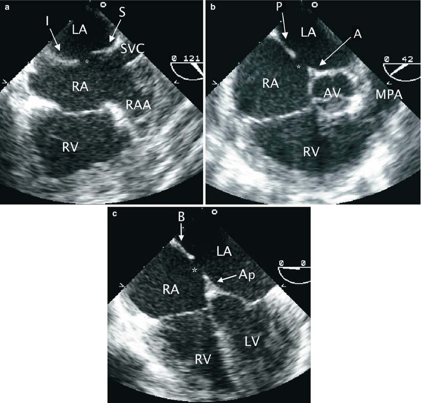
Fig. 17.2
Rims of secundum atrial septal defect (ASD). The rims of a secundum ASD are characterized in multiple TEE views. (a) Mid esophageal bicaval view with leftwards probe shaft rotation to display the superior (S) and inferior (I) rims of a secundum ASD (asterisk). (b) In a mid esophageal aortic valve short axis view, the anterior (A) and posterior (P) rims of the defect (asterisk) are seen. (c) Mid esophageal four chamber view is shown demonstrating the basal (B) and apical (Ap) rims of the defect (asterisk). AV aortic valve, LA Left atrium, LV left ventricle, MPA main pulmonary artery, RA right atrium, RAA right atrial appendage, RV right ventricle, SVC superior vena cava
The proper size device is selected to be ±2 mm of the stop flow balloon diameter. The balloon is then removed leaving the guide wire in place. An appropriate size sheath is positioned over the wire into a pulmonary vein or left atrium. A cable with the occluder device is advanced to the distal tip of the sheath. The tip of the delivery sheath is positioned in the mid left atrium, which is confirmed best by TEE imaging in the ME AV SAX view. The sheath is retracted over the cable to open the left atrial disc of the device. TEE confirms that the disc indeed is in the left atrium and has not opened in a pulmonary vein [26]. The cable and sheath are then withdrawn so that the left atrial disc is pulled closer to the atrial septum. The connecting waist is then partially deployed within the left atrium and then pulled back into the ASD to stent the defect. The right atrial disc is then deployed and the device stability is assessed as the arms of the device straddle the defect. Color Doppler assists in the determination of appropriate occlusion of the interatrial communication.
It is essential to have continuous TEE monitoring of the deployment at this stage to demonstrate capture of the rims of the ASD within the two discs of the occluder. Multiple TEE views, as described above, should be utilized to confirm this. If the device is not well positioned it can be retrieved and repositioned. When the device is confirmed to be in good position, the patency of the right upper pulmonary vein, superior vena cava, inferior vena cava, and coronary sinus are assessed by TEE, as is the presence of any mitral or tricuspid valve regurgitation using appropriate multiplane imaging for each structure as described throughout this textbook. The device is then released. Due to slight tension of the delivery cable, there is often a notable change in the angle of the device as it is released and self-centers within the defect and aligns with the interatrial septum. After deployment, TEE is used to image the device and a repeat assessment for residual shunts, vessel patency and valve competency is performed. Frequently, there is flow detected by color Doppler due to “foaming” within the device disks immediately after release. This does not represent significant shunting and should not be considered abnormal. The steps involved in transcatheter ASD occlusion with corresponding TEE imaging are summarized in Table 17.1, and imaging sequences are shown in Fig. 17.3.
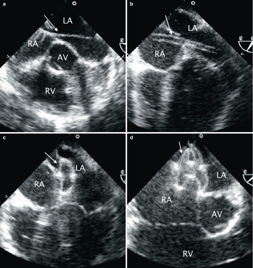
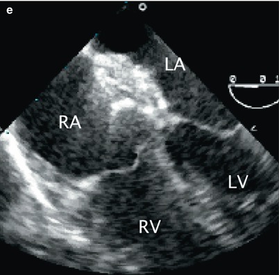
Table 17.1
Transesophageal echocardiography during trancatheter occlusion of atrial septal defect
Baseline complete TEE study to survey the defect and exclude additional lesions. Specifically, locate the defect, size and surrounding rims, most importantly the inferior, superior, and posterior rims. |
Demonstrate successive guidewire, catheter, sheath, and occluder delivery within the sheath. Suggested imaging planes: mid esophageal four chamber and mid esophageal bicaval views. Additional mid esophageal and deep transgastric views can also be used for complementary imaging. |
Demonstrate the deployment, in succession, of the left disc, waist, and right disc with capture of interatrial septum between the right and left discs. Suggested imaging planes: mid esophageal four chamber and mid esophageal bicaval views. Additional mid esophageal views can also be used for complementary imaging. |
Two-dimensional and color flow Doppler assessment for any residual shunt or valve injury/encroachment prior to device release. |
Repeat of the above after device release to demonstrate adequate device position, absence of residual shunt, venous obstruction, or valve injury. |
Fig. 17.3
Sequence of transcatheter occlusion of secundum atrial septal defect (ASD). (a) TEE image in the mid esophageal aortic valve short axis view demonstrating a guide wire (arrow) crossing the interatrial septum through an ASD during transcatheter device occlusion. (b) Following guidewire placement across the ASD, well into the left atrium/pulmonary vein, a sheath (arrow) is advanced across the ASD as shown in this mid esophageal view. (c) After deployment of the left atrial disc of occluder device (arrow), (d) the right disk (arrow) is opened. Note the appearance of the waist between the two discs. (e) After the occluder has been released, the position of the device relative to surrounding structures should be evaluated. As demonstrated in this mid esophageal four chamber view, there should be no impingement of the device on the atrioventricular valves. AV aortic valve, LA Left atrium, LV left ventricle, RA right atrium, RV right ventricle
Although intracardiac echocardiography may be utilized during ASD occlusion [27], TEE remains the main imaging approach for guiding these procedures at many institutions.
Transcather Occlusion of Ventricular Septal Defects
Transesophageal imaging of ventricular septal defects (VSDs) is described in Chap. 9. Transcatheter closure of VSDs has been well described [14, 17, 18]. Currently, only muscular and perimembranous VSDs are amenable to transcatheter device closure. At the time of this writing, the only device approved in the United States for closure of muscular VSDs is the Amplatzer® muscular VSD occluder (St. Jude Medical, St. Paul, MN). As described in the previous section regarding transcatheter closure of ASDs, in order to understand the manner in which TEE may guide VSD closure procedures, it is appropriate to review the steps involved. The description that follows applies to the use of the Amplatzer® device.
The Amplatzer® muscular VSD occluder is designed specifically for the muscular septum. The waist of the device, which centers and fills the defect, measures 7 mm in length. The left and right ventricular disks are 8 mm larger than the connecting waist in all but the smallest size device. Various occluder sizes are available, ranging from device size/waist diameter of 4 mm (corresponding disk diameter of 9 mm) to device size/waist diameter of 18 mm (corresponding disk diameter of 26 mm). These muscular defects can be closed using percutaneous or perventricular techniques.
Although percutaneous closure of a single muscular VSD is feasible without TEE guidance, many centers consider that TEE provides information not readily available by fluoroscopy, such as the relationship between the device and the mitral and tricuspid valve leaflets, and thus the use of this imaging modality is beneficial. For multiple defects (“Swiss cheese septum”) it is considered that TEE is mandatory to identify the location of the defects, the relationship of these to surrounding structures, and to enhance the overall safety and success of the intervention.
Routine right and left heart catheterization is performed to assess the degree of shunting, evaluate the pulmonary vascular resistance, and to perform angiography to define the location, size, and number of ventricular communications. A complete TEE study is undertaken from the standard imaging locations. The views that allow for assessment of the ventricular septum represent the focus of the examination as described in Chap. 9. Any associated cardiovascular abnormalities should be characterized and gross assessment of chamber size and ventricular function should be made. Specific attention is then paid to the VSD(s) and nearby structures, including the aortic and atrioventricular valves, papillary muscles, moderator band, and chordae tendineae. The atrioventricular valves are interrogated at baseline for any degree of regurgitation.
The appropriate device size is chosen to be 1–2 mm larger than the VSD size as assessed by TEE or angiography at end-diastole (the larger of the two diameter estimates). The next step in the closure sequence is to place a sheath across the defect. This is accomplished in a variety of ways. The most common approach used for mid muscular VSD device closure is to advance a catheter via retrograde catheterization from the left ventricle (LV) across the VSD into the right ventricle (RV). An exchange wire is advanced through the VSD and the RV into either branch pulmonary artery or retrograde through the tricuspid valve into the superior vena cava. In the latter case the wire is then snared and exteriorized through the right internal jugular vein. This provides a stable arteriovenous loop and allows a sheath to be advanced over the wire, from the right jugular vein to the RV and positioned into the LV across the VSD.
Larger mid muscular or apical VSDs can be easily crossed from the RV. However, there is an increased risk of entrapment in the trabeculae of the RV. Once the catheter crosses into the LV, an exchange guide wire is positioned into the LV apex and a delivery sheath is advanced over this wire and positioned into the body of the chamber. TEE and angiography are helpful in guiding device position. The LV disk is deployed in the middle of the LV cavity. Then, the entire assembly (cable/sheath) is pulled towards the interventricular septum with further retraction of the sheath to expand the waist within the VSD. Repeat TEE and angiography confirms device position. Assessment of mitral valve function is essential prior to deployment of the RV disk. It is important to assess the device position in multiple planes. Once proper position is confirmed, further retraction of the sheath to expand the RV disk is performed. Again, prior to device release, repeat TEE and angiography are performed. After deployment, TEE imaging allows for confirmation of device placement, assessment of residual shunting and/or any obstruction or regurgitation induced by the device. With release of the device and elimination of all tension, the device orientation frequently changes, which allows it to align with the ventricular septum. If there are any additional defects, they are occluded in similar fashion. A summary of the steps for transcatheter muscular VSD occlusion with suggested TEE imaging is provided in Table 17.2. Corresponding TEE images are shown in Fig. 17.4.
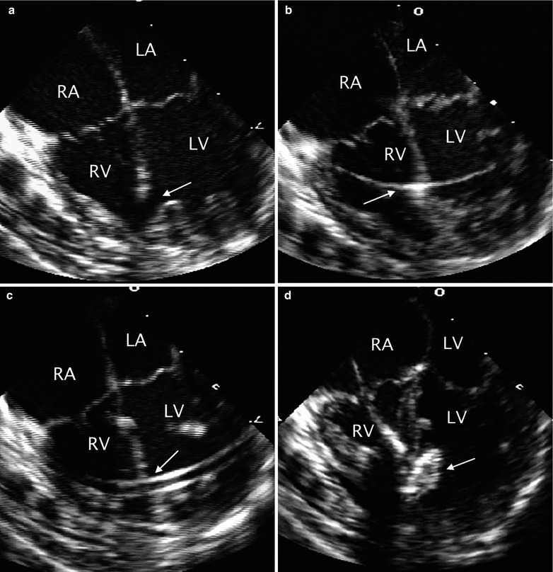
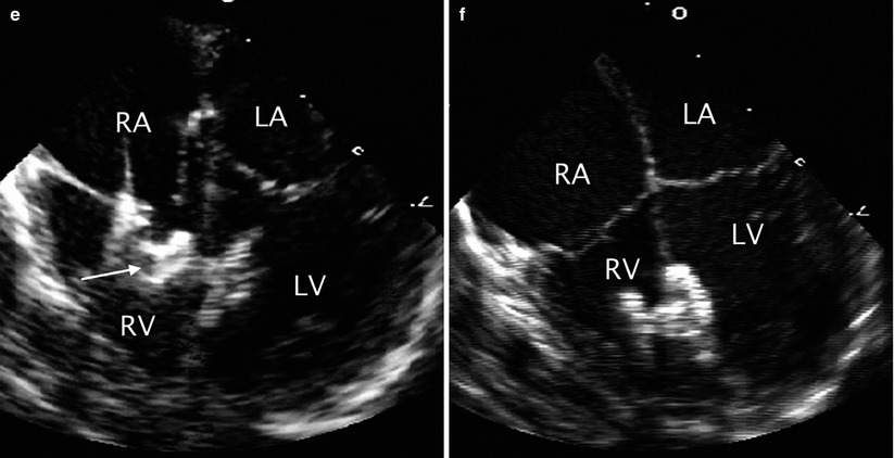
Table 17.2
Transesophageal echocardiography during trancatheter occlusion of ventricular septal defect
Baseline complete TEE study to survey the ventricular septal defect and exclude additional lesions. Specifically, locate the defect, size, surrounding rims and whether or not the rims are in close proximity to valves or other structures that may cause potential injury. |
Demonstrate successive guidewire, catheter, sheath, and occluder delivery within the sheath. Suggested imaging planes: mid esophageal four chamber, transgastric short axis and occasionally, mid esophageal long axis view. |
Demonstrate the deployment, in succession, of the left disc, waist, and right disc with capture of interventricular septum between the right and left discs. Suggested imaging planes: mid esophageal four chamber and transgastric short axis, and occasionally, transgastric long axis and mid esophageal long axis view views. |
Two-dimensional and color flow Doppler assessment for any residual shunt or valve injury/encroachment prior to device release. |
Repeat the above after device release to demonstrate adequate device position, and absence of residual shunt, venous obstruction, or valve injury. |
Fig. 17.4


Sequence of transcatheter occlusion of muscular ventricular septal defect (VSD). (a) TEE image in the mid esophageal four chamber view demonstrating a muscular VSD (arrow) near the apex of the heart. During transcatheter occlusion of the defect the intervention is facilitated by TEE monitoring. The sequential steps in the procedure include: (b) guidewire placement across the defect (arrow), (c) sheath positioning (arrow), (d) opening of the left disc (arrow) of the occluder, and (e) subsequent opening of the right disc (arrow) followed by release of the device. (f) The position of the device after deployment is then assessed. LA left atrium, LV left ventricle, RA right atrium, RV right ventricle
Stay updated, free articles. Join our Telegram channel
Full access? Get Clinical Tree
