Aortic Valve, Aorta, and Aortic Branches
Transesophageal echocardiography (TEE) can substantially augment the transthoracic echocardiogram in the workup of the aortic valve and the aorta.
Aortic Valve
Views
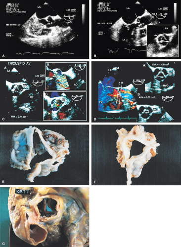
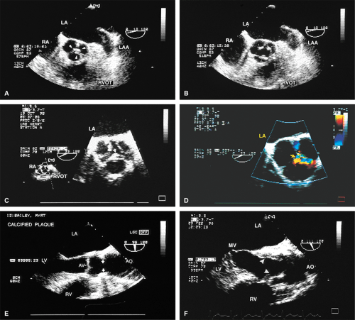
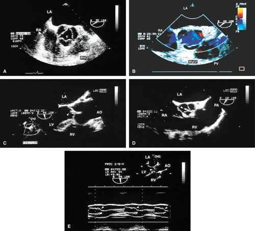
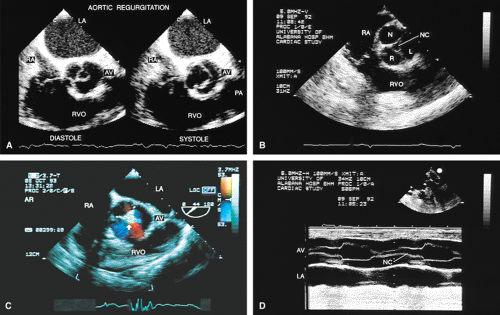
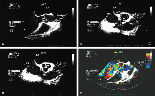
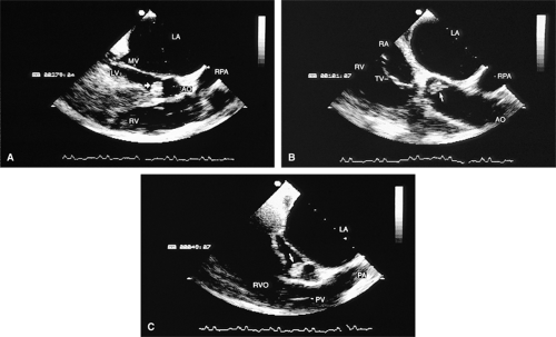
The mid-esophageal short- and long-axis views are the most commonly used views. To obtain an optimal short-axis view, the TEE image is rotated from 0° to between 30° and 60°, with flexion of the probe as necessary. The optimal short-axis view is the one in which the valve appears most circular and the three thin leaflets are seen clearly, surrounded by the noncoronary cusp in the upper left and the left and right cusps as one looks clockwise from the noncoronary cusp. This view is particularly useful for determining the number of aortic valve leaflets and assessing their thickening and fusion, as well as for determining the area of the aortic valve and diagnosing and assessing the severity of aortic insufficiency. The approach to positioning for aortic valve planimetry to obtain valve area is discussed in the subsequent text.
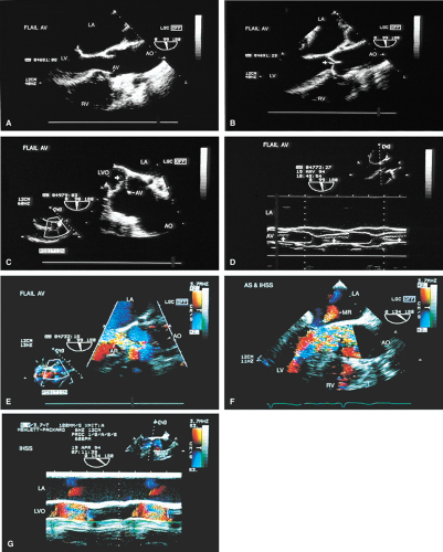
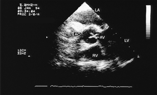
The long-axis view of the aortic valve is generated by further rotation of the probe to an angle usually between 90° and 160°, again with flexion as necessary, to optimize the image. This view demonstrates the aortic outflow tract (AOT), aortic valve and sinuses of Valsalva, and the proximal aorta. The normal valve leaflets appear as thin, pliable, widely opening structures. It is important not to misdiagnose the normal mild thickenings at the coaptation point of the aortic valve leaflets (nodules of Arantius) as pathologic. This view is particularly useful for determining the level of aortic outflow obstruction: subvalvular, valvular, or supravalvular. Leaflet structure and separation are well seen in this view. The presence of valve redundancy can be assessed and can be generally distinguished from the presence of vegetation. Eversion of the leaflets (“rolling up” of the edges) is also well demonstrated.
A less commonly used view is the deep transgastric view, the central utility of which is to try to align the ultrasound beam with the aortic jet in order to determine the pressure gradient across the aortic valve. These views are obtained by advancing the scope into the transgastric position and then flexing it to obtain a view that places the aorta and aortic valve in line with the ultrasound beam. This facilitates the measurement of gradients but does not allow sufficient maneuver to ensure that the probe is aligned so as to provide the highest velocity aortic jet.
Aortic Outflow Obstruction
Using TEE, it is possible to diagnose aortic outflow obstruction, determine the level (subvalvular, valvular, or supravalvular), and quantify the severity. Aortic stenosis (AS) is the only valvular lesion commonly associated with sudden cardiac death. It becomes more common with advancing age, so a progressively aging population results in an increase in the prevalence of the lesion. Subvalvular and supravalvular outflow obstruction are less common.
When an adequate study is performed, transthoracic echocardiography (TTE) can be effective for the workup of AS. On TTE, the diagnosis of AS is made by demonstrating a thickened aortic valve and either a high (>approximately 50 mm Hg) transvalvular gradient or a diminished aortic valve area (AVA) (using the continuity equation). In order to estimate the gradient, the beam is aligned with the axis of the highest velocity aortic jet and the velocity recorded. This may require interrogating in multiple views, including the apical five-chamber, suprasternal notch, and right parasternal views. Using a simplified conservation of energy (Bernoulli) equation, the peak gradient is
Δ Pmax = 4 (Vmax – VOT)2
where Vmax is the peak aortic velocity and VOT is the outflow tract velocity. The mean aortic gradient can also be estimated using the time velocity integral.
An indirect calculation of the AVA can be obtained from the continuity equation, which is a statement of the
conservation of mass. Assuming the AOT to be circular, its area (AOT) can be estimated from the measured diameter on the parasternal long-axis view and the outflow tract velocity (VOT), obtained from pulsed-Doppler examination in the parasternal five-chamber view. The peak velocity across the aortic valve is known, and with a variety of simplifying assumptions, the AVA is calculated as
conservation of mass. Assuming the AOT to be circular, its area (AOT) can be estimated from the measured diameter on the parasternal long-axis view and the outflow tract velocity (VOT), obtained from pulsed-Doppler examination in the parasternal five-chamber view. The peak velocity across the aortic valve is known, and with a variety of simplifying assumptions, the AVA is calculated as
AVA = VOTAOT/Vmax
This equation is valid even in the presence of aortic insufficiency.
In patients with a markedly reduced stroke volume, valve opening can be reduced. Therefore, the low stroke volume results in both a reduced pressure gradient and a smaller valve area. In patients with a low gradient due to low stroke volume, a dobutamine infusion can be used to clarify the picture. With inotropic stimulation, the computed valve area of a normal valve (or one that is not rigid or severely stenosed) will increase with a minimal rise in gradient. A more rigid, severely stenosed valve, on the other hand, will demonstrate an increase in the transvalvular gradient without an increase in the computed valve area.
These same calculations can be performed on the basis of data derived from the TEE transgastric views. However, in practice, this approach is rarely used. The appropriate deep transgastric view is hard to obtain and it is not possible to maneuver the view sufficiently to be certain that the maximum jet is found.
TEE has assumed a prominent role in the echocardiographic examination of the aortic valve because of the superior imaging detail that it provides compared to TTE. Because the multiplane probe permits great flexibility in the selection of the imaging plane, it is far more effective than single and biplane probes in providing a complete study of a variety of lesions. TEE should be considered a complement to, but not a replacement for, TTE.
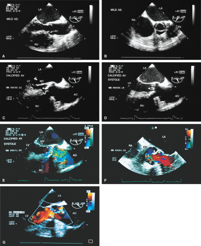
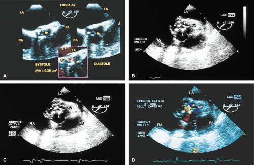
A number of findings suggest or are consistent with AS. Thickening of the aortic valve is clearly seen on TEE; when limitation of motion is also present, this is consistent with AS. Color Doppler detection of a narrow (7 mm or less at its origin) systolic jet indicates severe stenosis.
Planimetry of the minimum orifice area in the short-axis view (usually best imaged at 30° to 60°) has been shown to correlate well with catheterization-derived AVA. The stenotic valve often has the geometry of a truncated cone. It is important that the topmost part of this cone be studied, because it is the flow-limiting orifice. To ensure that the minimum orifice is imaged, the probe is first moved up the esophagus in the short-axis view until the aortic valve disappears. The probe is then advanced until the full perimeter of the valve just comes into view, which should demonstrate the minimum cross-sectional area (flow-limiting orifice). Gain must be carefully adjusted to minimize the “blooming” effect of the extensive calcium that is usually present in adults, and the probe must be manipulated to avoid acoustic shadowing by the calcium. In the presence of severe calcification it may be difficult to identify the orifice. When this difficulty arises, color Doppler is often helpful because the first signals appear in the orifice at the beginning of systole.
An attempt can be made to position the TEE image so that a pressure gradient can be measured between the left ventricle and the aorta using the transgastric view. If a high gradient is obtained, AS can be diagnosed. However, it is difficult to be certain that the maximum gradient has been measured because TEE has limited capacity for looking for the maximum jet at multiple angles.
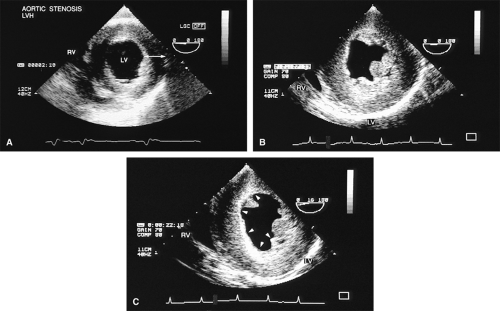
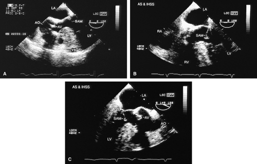
Left ventricular hypertrophy is well imaged by TEE and commonly accompanies AS. It is particularly important to exclude the presence of coexisting hypertrophic cardiomyopathy (HCM) because the hypertrophied muscle can be resected at the time of aortic valve replacement. A narrow left ventricular outflow tract (LVOT) (<20 mm) and hypertrophy that is out of proportion to what would be expected from the degree of AS present alert the echocardiographer to the possibility of coexisting HCM. Systolic anterior motion of the mitral valve may be absent in HCM patients with severe AS.
An interesting lesion that can be identified by TEE is the supravalvular AS. This lesion may be congenital, or it may be present in patients with atherosclerosis and very high cholesterol levels.
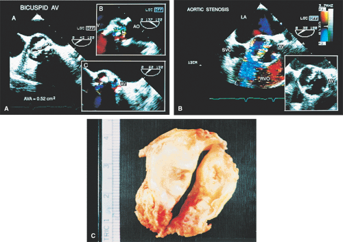
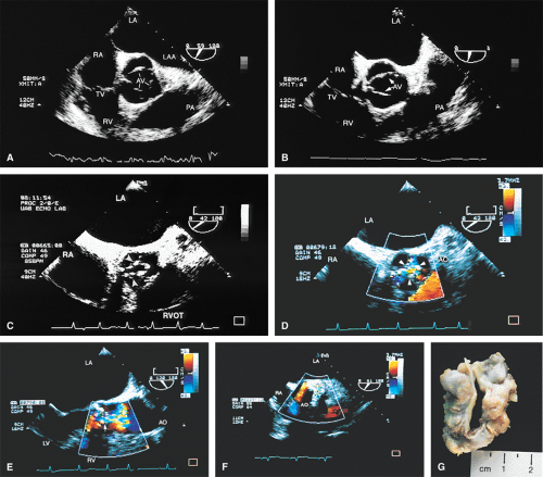
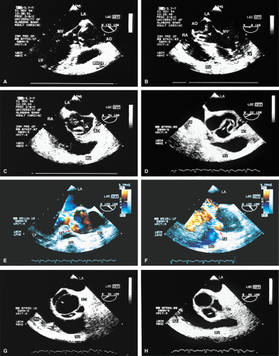
The morphologic data available from TEE allow detailed examination of the aortic valve. The multiplane probe is substantially more effective than are single or biplane probes. The mild thickening normally present at the points of leaflet coaptation (nodules of Arantius) also may be identified. TEE effectively defines the number of leaflets and the degree of commissural fusion present. The median raphe of a bicuspid valve can be clearly seen. The distinction between tricuspid and bicuspid aortic valve is important because of the difference in prognosis and the implications for valve repair versus valve replacement. The presence of valve redundancy, which may be confused with a vegetation on transthoracic echo, can be delineated. Eversion of the leaflets is also well demonstrated.
Aortic Regurgitation
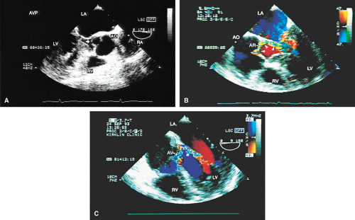
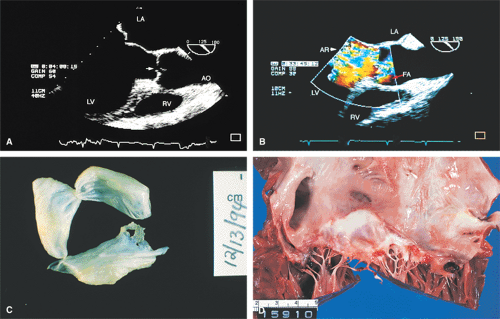
The causes of aortic regurgitation (AR), including thickening, eversion of the leaflets, infection, dilatation of the proximal aorta with loss of leaflet coaptation, and redundancy, can be delineated. Intermittent AR, caused by varying coaptation points resulting from valve redundancy (especially in a bicuspid valve), can also be detected. Small fenestrations as well as large holes and their exact location and size can be imaged.
TEE is of particular importance in the workup for endocarditis. TEE is far more sensitive for the assessment of vegetations than is TTE. For this reason, in the
appropriate clinical setting, the absence of a vegetation on TTE should prompt the performance of TEE. Abscesses are also far more likely to be seen on TEE than TTE. Their anatomic location and extent are readily imaged, and their communication with other structures is diagnosed using color-flow Doppler.
appropriate clinical setting, the absence of a vegetation on TTE should prompt the performance of TEE. Abscesses are also far more likely to be seen on TEE than TTE. Their anatomic location and extent are readily imaged, and their communication with other structures is diagnosed using color-flow Doppler.
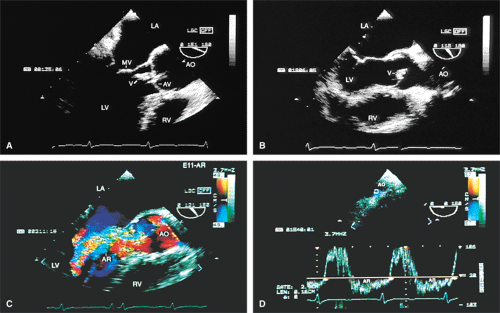
Assessment of the severity of AR is based on semiquantitation using the fraction of the LVOT at the origin of the diastolic jet on the ventricular aspect of the aortic valve that is covered by the jet. The percent ratio of proximal jet width to LVOT diameter (taken at the same location) of <25% represents mild regurgitation, 25% to 65% represents moderate severity, and >65% is a demonstration of severe regurgitation. Two technical points are important. First, the assessment must be made at the origin of the jet (vena contracta level). Second, the Nyquist limit is important. If it is set higher than 40 to 50 cm/sec, changes in the color filter result in the loss of imaging of lower velocities and therefore changes the size of the proximal jet.
Aorta
Defining aortic anatomy is another important application of TEE. The location and extent of aortic aneurysms are more effectively visualized using TEE than TTE. The ability of TEE to image the entire aorta is an important advantage over TTE. Evidence of rupture can be sought and the extent of associated AR can be assessed using color-flow Doppler. In many centers, TEE is the modality of choice for diagnosing aortic dissection because of its ability to rapidly and accurately make the diagnosis. This is important because these patients may die suddenly if surgery is not performed immediately.
The diagnosis of dissection is based on the demonstration of a flap that separates the true lumen (TL) and the false lumen (FL). It is necessary to examine the aorta in multiple planes because the flap is not well seen in all views. The flap is usually, but not always, mobile, which aids in making the diagnosis. Flow in opposite directions on the different sides of the flap, if present, helps to confirm the diagnosis. A number of features aid in differentiating the TL from the FL and may help confirm the diagnosis of aortic dissection. Flow in the TL usually has higher velocity than flow in the FL; as a result, the signals are generally brighter. In addition, the TL expands in systole and the FL expands in diastole. When a clot is present it is usually in the FL. Communications between the TL and FL seen on color Doppler are helpful in confirming the diagnosis. Because the entire thoracic and proximal abdominal aorta can be imaged using the multiplane probe, the exact location and full extent of dissection can be delineated.
Dissections that involve the ascending aorta, arch, or both, and the descending aorta are DeBakey type I. Dissections that involve the ascending aorta, arch, or both (but not the descending aorta) are DeBakey type II, and those that involve only the descending aorta are Type III. In the Stanford classification, any dissection involving the ascending aorta, the arch, or both is type A, whereas dissection involving only the descending aorta is type B.
TEE is useful in assessing prognosis and making management decisions. A clotted FL has a better prognosis than a flow-filled FL because it acts as a buttress for the TL, thereby diminishing the chance of rupture. Assessment of the cause and severity of AR in patients who had dissection helps in making a decision regarding the necessity of resuspension or replacement of the aortic valve. Involvement of the coronary arteries in the dissection can also be diagnosed. Dissections that involve only the descending aorta do not require surgery unless there is evidence of impending rupture or compromise of organ flow, which occurs rarely.
Atherosclerotic plaques in the aorta are readily identified by TEE. The presentation varies from uniform intimal thickening to large mobile plaques protruding into the lumen. Atherosclerosis in the aorta is a risk factor for stroke and emboli to other parts of the body. The greater the mobility, the higher the risk of embolization. Fixed plaques protruding >5 mm into the lumen are also at high risk for embolization.
Stay updated, free articles. Join our Telegram channel

Full access? Get Clinical Tree


