3 Angiography for Percutaneous Coronary Interventions 
1. Establish the relationship of coronary ostium to aorta for guide catheter selection.
2. Verify target vessel, pathway, and angle of entry.
3. Confirm lesion length and morphology using additional angulated views eliminating vessel overlap.
4. Separate associated side branches and degree of ostial atherosclerosis.
5. Visualize distribution of collateral supply.
6. Determine the true (maximally vasodilated) diameter of the coronary artery at the target site.
Classical terminology for angiographic projections with regard to left and right anterior oblique, cranial and caudal angulation, and lateral projections remains as defined in previous discussions of diagnostic coronary angiography (see The Cardiac Catheterization Handbook, 5th edition, Chapter 4).
Common Angiographic Views for Angioplasty
The routine coronary angiographic views described below should include those that best visualize the origin and course of the major vessels and their branches in at least two different (preferably orthogonal) projections. Naturally, there is a wide variation in coronary anatomy, and appropriately modified views will need to be individualized. The nomenclature for angiographic views is described in Chapter 4 of The Cardiac Catheterization Handbook, 5th edition, but will be reviewed briefly here, emphasizing the interventionalist’s thinking.
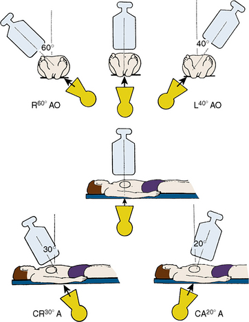
Position for Anteroposterior Imaging
The image intensifier is directly over the patient, with the beam perpendicular to the patient lying flat on the x-ray table (Figs. 3-1, 3-2). The anteroposterior (AP) view or shallow right anterior oblique (RAO) displays the left main coronary artery in its entire perpendicular length. In this view, the branches of the left anterior descending (LAD) and left circumflex coronary arteries branches overlap. Slight RAO or left anterior oblique (LAO) angulation may be necessary to clear the density of the vertebrae and the catheter shaft in the thoracic descending aorta. In patients with acute coronary syndromes, this view will exclude left main stenosis, which can preclude or complicate PCI. The AP cranial view is excellent for visualizing the LAD with septals moving to the left (on screen) and diagonals to the right, helping wire placement.
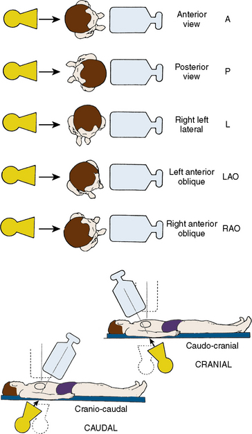
Figure 3-1 Nomenclature for angiographic views.
(Modified from Paulin S. Terminology for radiographic projections in cardiac angiography. Cathet Cardiovasc Diagn 1981;7:341.)
Position for Left Anterior Oblique Imaging
In the LAO position, the image intensifier is to the left side of the patient. The LAO/cranial view also shows the left main coronary artery (slightly foreshortened), LAD, and diagonal branches. Septal and diagonal branches are separated clearly. The circumflex and marginals are foreshortened and overlapped. Deep inspiration will move the density of the diaphragm out of the field. The LAO angle should be set so that the course of the LAD is parallel to the spine and stays in the “lucent wedge” bordered by the spine and the curve of the diaphragm. Cranial angulation tilts the left main coronary artery down and permits view of the LAD/circumflex bifurcation (Fig. 3-3). Too steep an LAO/cranial angulation or shallow inspiration produces considerable overlapping with the diaphragm and liver, degrading the image.
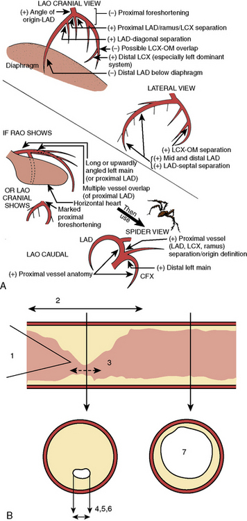
The LAO/caudal view (“spider” view; Fig. 3-3) shows a foreshortened left main coronary artery and the bifurcation of the circumflex and LAD. Proximal and mid portions of the circumflex and the origins of obtuse marginal branches are usually seen excellently. Poor image quality may be due to overlapping of diaphragm and spine. The LAD is considerably foreshortened in this view.
Angulations for Saphenous Bypass Grafts
Coronary artery saphenous vein grafts are visualized in at least two views (LAO and RAO). It is important to show the aortic anastomosis, the body of the graft, and the distal anastomosis. The distal runoff and continued flow or collateral channels are also critical. The graft vessel anastomosis is best seen in the view that depicts the native vessel best. A general strategy for graft angiography is to perform the standard views while assessing the vessel key views for specific coronary artery segments (Table 3-1) to determine the need for contingency views or an alteration/addition of special views. Therefore, the graft views can be summarized as follows:
1. RCA graft: LAO cranial/RAO and lateral
2. LAD graft (or internal mammary artery): lateral, RAO cranial, LAO cranial, and AP (the lateral view is especially useful to visualize the anastomosis to the LAD)
3. Circumflex (and obtuse marginals) grafts: LAO and RAO caudal.
Table 3-1 Recommended “Key” Angiographic Views for Specific Coronary Artery Segments
| Coronary Segment | Origin/Bifurcation | Course/Body |
|---|---|---|
| Left main | AP | AP |
| LAO cranial | LAO cranial | |
| LAO caudal* | ||
| Proximal LAD | LAO cranial | LAO cranial |
| RAO caudal | RAO caudal | |
| Mid LAD | LAD cranial | |
| RAO cranial | ||
| Lateral | ||
| Distal LAD | AP | |
| RAO cranial | ||
| Lateral | ||
| Diagonal | LAO cranial RAO cranial | RAO cranial, caudal, or straight |
| Proximal circumflex | RAO caudal | LAO caudal |
| LAO caudal | ||
| Intermediate | RAO caudal | RAO caudal |
| LAO caudal | Lateral | |
| Obtuse marginal | RAO caudal | RAO caudal |
| LAO caudal | ||
| RAO cranial (distal marginals) | ||
| Proximal RCA | LAO | |
| Lateral | ||
| Mid RCA | LAO | LAO |
| Lateral | Lateral | |
| RAO | RAO | |
| Distal RCA | LAO cranial | LAO cranial |
| Lateral | Lateral | |
| PDA | LAO cranial | RAO |
| Posterolateral | LAO cranial | RAO cranial |
| RAO cranial | RAO cranial |
AP, anteroposterior; LAD, left anterior descending; LAO, left anterior oblique; PDA, posterior descending artery (from RCA); RAO, right anterior oblique; RCA, right coronary artery.
From Kern MJ, ed. The cardiac catheterization handbook, 2nd ed. St Louis, MO: Mosby, 1995: 286.
Techniques for Coronary Arteriography
Power Injection Versus Hand Injection for Coronary Arteriography
• Right coronary artery: 6 mL at 2–3 mL/sec; maximum pressure 450 psi
• Left coronary artery: 10 mL at 4–6 mL/sec; maximum pressure 450 psi
Angiographic TIMI Classification of Blood Flow
Thrombolysis in myocardial infarction (TIMI) flow grading has been used to assess, in a qualitative fashion, the degree of restored perfusion achieved after thrombolysis or angioplasty in patients with acute myocardial infarction. Table 3-2 provides descriptions used to assign TIMI flow grades.
Table 3-2 Thrombolysis in Myocardial Infarction (TIMI) Flow: Grade and Blush Scores
| TIMI Flow Grade | Description |
|---|---|
| Grade 3 (complete reperfusion) | Anterograde flow into the terminal coronary artery segment through a stenosis is as prompt as anterograde flow into a comparable segment proximal to the stenosis. Contrast material clears as rapidly from the distal segment as from an uninvolved, more proximal segment. |
| Grade 2 (partial reperfusion) | Contrast material flows through the stenosis to opacify the terminal artery segment. However, contrast enters the terminal segment perceptibly more slowly than more proximal segments. Alternatively, contrast material clears from a segment distal to a stenosis noticeably more slowly than from a comparable segment not preceded by a significant stenosis. |
| Grade 1 (penetration with minimal perfusion) | A small amount of contrast flows through the stenosis but fails to fully opacify the artery beyond. |
| Grade 0 (no perfusion) | There is no contrast flow through the stenosis. |
| Myocardial Blush Grade | |
0 No myocardial blush or contrast density. Myocardial blush persisted (“staining”). 1 Minimal myocardial blush or contrast density. 2 Moderate myocardial blush or contrast density but less than that obtained during angiography of a contralateral or ipsilateral noninfarct-related coronary artery. 3 Normal myocardial blush or contrast density, comparable with that obtained during angiography of a contralateral or ipsilateral noninfarct-related coronary artery. | |
Modified from Sheehan F, Braunwald E, Canner P, et al. The effect of intravenous thrombolytic therapy on left ventricular function: a report on tissue-type plasminogen activator and streptokinase from the Thrombolysis in Myocardial Infarction (TIMI) Phase I Trial. Circulation 1987;72:817–829.
Classification of Distal Angiographic Contrast Runoff
The distal runoff is classified into four stages (also known as TIMI grade):
TIMI Frame Count
Stay updated, free articles. Join our Telegram channel

Full access? Get Clinical Tree


