A Word About Doppler Controls
On every ultrasound machine, there are several controls that are always the same (although they may not be arranged in the same way). It is important to understand these controls in order to optimize your image and to not create pathology when there is none. Although we will be focusing on the basic Doppler controls, there are also some gray-scale controls that are important as well. Please note that this book does not cover all the controls available on ultrasound machines and is not intended to cover ultrasound physics.
I. BASIC GRAY-SCALE CONTROLS
A. Overall Gain and Time-Gain Compensation (TGC).
These are found on the machine as a round knob and usually a series of sliding switches, respectively. They control the gray-scale gain, or the strength of the signal (the TGC controls the gain at different levels of the image). They control the “brightness” of the image. It is important to maintain the proper gain throughout the image and to not have it be too bright in some areas and not in others. When you have an image that is too bright in the near field and too dark in the far field, this is the time to use your TGC (Fig. 9.1). Adjust the slides until your image is more homogeneous (Fig. 9.2). When the image is too dark or too light overall, this is the time to use your overall gain (Figs. 9.3 and 9.4).
B. Depth.
This is a switch that sets the depth of the image. It is important to adjust this according to which body part you are evaluating. A vein in a leg, for example, needs a greater depth than a carotid artery. Adjust your depth so that you have a clear image in the center of the screen. When looking at a superficial structure, decrease the depth to eliminate all of the useless information posterior to that structure (Fig. 9.5).
C. Focus.
This is an important switch that is often overlooked. It is important to place the level of the focus (often displayed as an arrow or a triangle on the right hand side of the screen) at the level of the structure you are looking at. This not only optimizes your gray-scale image by providing a clearer image, but it optimizes your color image as well (Fig. 9.6).
II. BASIC COLOR CONTROLS
A. Steer.
This is a switch that steers the direction of the color box. It is important to steer the box along the direction of the vessel to achieve a good Doppler angle. Most ultrasound machines allow you to steer the box to the right, to the left, and center or straight down. If the vessel is sloped down to the right side of the screen, then the box should be angled along with it (Fig. 9.7). If the box is not properly steered, color will not fill the lumen of the vessel properly and could be mistaken for occlusion, plaque, or thrombus by an untrained eye (Fig. 9.8). If the vessel already dives at a sharp angle, then the center position may be used. Another way to adjust this is to “heeltoe” or rock the transducer to angle the vessel in the plane that fits the color box. This is important to do when a vessel is perpendicular to the beam and runs horizontal across the screen. With a 90-degree angle to flow, there is no frequency shift and therefore there will be little or no color in the center of the box. On one side there might be some degree of shift giving you one color, and on the other side the same with the opposite color. (On one side, flow is moving toward the transducer, and on the other side it is moving away from the transducer.)
B. Size.
This adjusts the size of the color box. The largest box that is appropriate for the area being examined should be used. The larger the box, the slower the frame rate, so if the frame rate seems slow, try decreasing the size of the box to cover just the area being examined. It is important to cover the whole area that you are evaluating (e.g., you don’t want to cut off half of the pseudoaneurysm that you are trying to evaluate). It is also important not to use a box that is too big that contains a lot of useless confusing information that could cause artifact. For example, when evaluating the left portal vein, narrow the box to include only the left portal vein. Opening the box wide often includes part of the heart, causing flash artifact. The box will change shape depending on which transducer you are using (linear- vs. curved-array).
C. Invert.
This is a switch that flips the color on the color map. The color map is the bar in the upper right
hand corner of the color image that displays red and blue (in varying shades) one on top of the other. Whichever color is on top is the color that is displayed toward the transducer. The color on bottom is away from the transducer. Often this is red displayed as towards the transducer, while blue is away from the transducer. The invert feature allows you to flip the map so that you may assign specific colors to specific vessels, such as blue to veins and red to arteries. It is important to know what the proper flow direction is and make sure that is the case before you change it. If you are scanning in a plane where you know that the portal vein flow should be toward the transducer and should be red as assigned by the color map and it is displayed as blue, this indicates that the flow is reversed (see Fig. 2.16). Remember that flow direction changes in response to the angle with the beam. If you rock the transducer to display the popliteal vein angled down to the right, the flow is toward the transducer and is displayed as red. If you rock the transducer to display the popliteal vein angled down to the left, the flow is away from the transducer and is displayed in blue.
hand corner of the color image that displays red and blue (in varying shades) one on top of the other. Whichever color is on top is the color that is displayed toward the transducer. The color on bottom is away from the transducer. Often this is red displayed as towards the transducer, while blue is away from the transducer. The invert feature allows you to flip the map so that you may assign specific colors to specific vessels, such as blue to veins and red to arteries. It is important to know what the proper flow direction is and make sure that is the case before you change it. If you are scanning in a plane where you know that the portal vein flow should be toward the transducer and should be red as assigned by the color map and it is displayed as blue, this indicates that the flow is reversed (see Fig. 2.16). Remember that flow direction changes in response to the angle with the beam. If you rock the transducer to display the popliteal vein angled down to the right, the flow is toward the transducer and is displayed as red. If you rock the transducer to display the popliteal vein angled down to the left, the flow is away from the transducer and is displayed in blue.
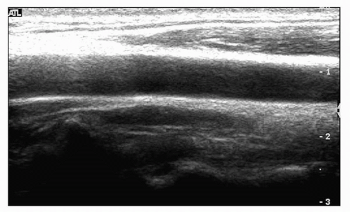 FIGURE 9.1. The image demonstrates that it is too bright in the near field and too dark in the far field, thus the TGC needs to be adjusted. |
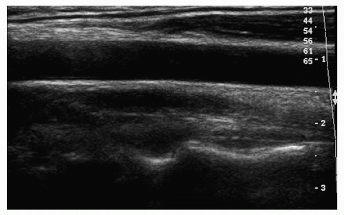 FIGURE 9.2. The time-gain compensation in the image in Fig. 9.1 has been adjusted, and the image is now more homogeneous. |
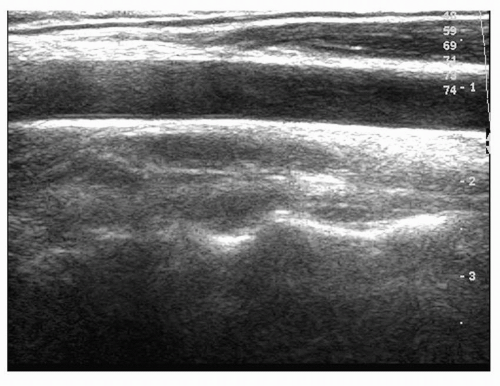 FIGURE 9.3. The overall gain in this image is too high (the image is too bright). |
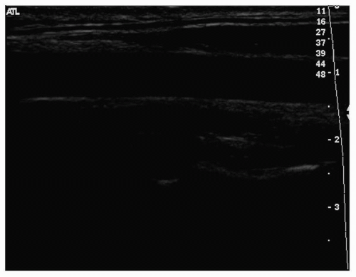 FIGURE 9.4. The overall gain in this image is darker than it should be. |
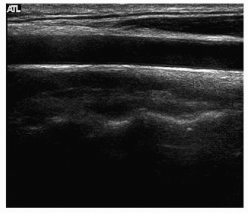 FIGURE 9.5. The depth in this image needs to be decreased, which will center the object of interest in the middle of the screen. |
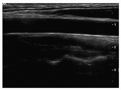 FIGURE 9.6. The focus in this image is set incorrectly. It needs to be moved up to the level of the object of interest, which is the carotid artery in this case.
Stay updated, free articles. Join our Telegram channel
Full access? Get Clinical Tree
 Get Clinical Tree app for offline access

|